• There were many reasons for the change of the site software, the biggest was security. The age of the old software also meant no server updates for certain programs. There are many benefits to the new software, one of the biggest is the mobile functionality. Ill fix up some stuff in the coming days, we'll also try to get some of the old addons back or the data imported back into the site like the garage. To create a thread or to reply with a post is basically the same as it was in the prior software. The default style of the site is light colored, but i temporarily added a darker colored style, to change you can find a link at the bottom of the site.

Something else to be aware of on 2020+ RT's - Brake switch issues!

Jetfixer

Well-known member
So I had my brake light switch fail on my 2020 RTL. Even though it's under warranty, no one near me had one in stock. So I ordered one from a dealer in VA. No problem. Unfortunately, most of the right side body panels must be removed to access the switch connector. The switch itself is easily reached without removing anything. However, in another shocking example of very poor engineering, the round switch has two nuts threaded on its body and appears to go through a bracket. It doesn't. The bracket is more like a fork shape that is open at the BOTTOM. If either of the two nuts vibrates loose, the switch will simply fall out and hang by its wires and the spring that pulls the plunger. That is absolutely unforgiveable. If they couldn't have the body of the switch captured completely (which they could have), then at least the fork should not be pointed down, which would also have been possible.
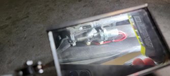
20211207_170746 (1).jpg

View looking up using a mirror. You can see the bracket is open at the bottom.


As a footnote, the switch that is still shown on all of the online parts catalogs has been superseded. No obvious difference, but perhaps internal changes.
 
Last edited:
Thanks for the heads up, Jetfixer. Here’s hoping that the ‘21 has the superseded part installed.:dontknow:

Pete
 
Thanks for the heads up, Jetfixer. Here’s hoping that the ‘21 has the superseded part installed.:dontknow:

Pete

:agree: .... the same issue with the ( now infamous ) DESS module. .... after mine failed in 2015 ( a 14RT ) after I got home I quickly moved the module ( and plug ) to just under the right headlight .... After that I could re-place it in about 5 min. in the dark :roflblack: ... It stayed there for two+ years untill " Joel the Biker " turned the unit off ...... just sayin .... Mike :thumbup:
 
That mounting style has been motorcycle practice for 50 years and most of us keep our nuts tight. You might thank BRP for adding the third wire (mine has only two) making the switch SPDT to provide continuous circuit continuity monitoring for an additional improvement in safe riding.
 
So Jet,
Did the switch fail because it vibrated loose from the bracket and dropped down???? or did it just fail on it's own? I'll be checking the security of my switch this afternoon. Thanks for the heads up.
 
So Jet,
Did the switch fail because it vibrated loose from the bracket and dropped down???? or did it just fail on it's own? I'll be checking the security of my switch this afternoon. Thanks for the heads up.

Mine just failed on its own, luckily in my garage. It set the CEL, Limp home, VSS fail, etc codes. All were active codes in BUDS that would not reset, and I confirmed the failure with a meter after getting to the connector.
 
Jetfixer -- please excuse my curiosity: did the linear actuation switch fail in its contracted or extended position or both?

I believe these are four circuit continuity failure modes:

Contracted or Extended -- open circuit on both signal wires
Contracted or Extended -- closed circuit on both signal wires

Thank you.

My switch failed in a bizarre way. If I pushed lightly on the brake pedal, the brake lights would flash one time extremely fast. Think like an old flash bulb. If I continued pressing harder, the brake lights would come on and stay on while held. If I pressed even harder, they would go off and stay off. Confirmed using a sensitive ohm meter after getting to the connector. Using the service manual, only two of the four contacts are used at all, (pins 3 & 4). This matches the wiring diagram also. The switch is called the Brake Light and Pressure Switch. My understanding of the system is that if the brake light switch is made, the system waits up to 15 seconds to see a rise in brake pressure. If there is no pressure rise, the nanny gets upset that the rider has the throttle Not Closed AND their foot on the brake pedal. If there IS a pressure rise and the throttle is still not closed, the nanny gets upset about that too. All of this computing is done by the VSS system, which explains the VSS fault when the switch acts up. Since the brake light switch circuit goes to the ECM, and is drawn on the wiring diagram as a simple open/closed switch, I'm not sure where the pressure signal comes from, unless it's actually derived from the switches' linear position ( which would make the wiring diagram symbol wrong) or perhaps the other two contacts actually ARE used for something that isn't on the wiring diagram (and would also make the symbol wrong), or the pressure is derived from somewhere else on the CANBUS that also is not shown on the wiring diagram; maybe through the anti-lock brake subsystem? There is definitely a pressure pick off somewhere in the system. BUDS can tell you what the brake pressure applied is. If this switch is actually truly linear AND part of the CANBUS, then a pressure signal can be determined by pedal and thereby switch travel. However, that's not how it's drawn on the wiring diagram.


EDIT Found the other two contacts (Pins 1 and 2) on the VCM wiring diagram. Still shown as only open or closed, and not as a linear pressure. Still not sure where the pressure is derived from...
 
Last edited:
My switch failed in a bizarre way. If I pushed lightly on the brake pedal, the brake lights would flash one time extremely fast. Think like an old flash bulb. If I continued pressing harder, the brake lights would come on and stay on while held. If I pressed even harder, they would go off and stay off. Confirmed using a sensitive ohm meter after getting to the connector. Using the service manual, only two of the four contacts are used at all, (pins 3 & 4). This matches the wiring diagram also. The switch is called the Brake Light and Pressure Switch. My understanding of the system is that if the brake light switch is made, the system waits up to 15 seconds to see a rise in brake pressure. If there is no pressure rise, the nanny gets upset that the rider has the throttle Not Closed AND their foot on the brake pedal. If there IS a pressure rise and the throttle is still not closed, the nanny gets upset about that too. All of this computing is done by the VSS system, which explains the VSS fault when the switch acts up. Since the brake light switch circuit goes to the ECM, and is drawn on the wiring diagram as a simple open/closed switch, I'm not sure where the pressure signal comes from, unless it's actually derived from the switches' linear position ( which would make the wiring diagram symbol wrong) or perhaps the other two contacts actually ARE used for something that isn't on the wiring diagram (and would also make the symbol wrong), or the pressure is derived from somewhere else on the CANBUS that also is not shown on the wiring diagram; maybe through the anti-lock brake subsystem? There is definitely a pressure pick off somewhere in the system. BUDS can tell you what the brake pressure applied is. If this switch is actually truly linear AND part of the CANBUS, then a pressure signal can be determined by pedal and thereby switch travel. However, that's not how it's drawn on the wiring diagram.


EDIT Found the other two contacts (Pins 1 and 2) on the VCM wiring diagram. Still shown as only open or closed, and not as a linear pressure. Still not sure where the pressure is derived from...
According to what I find in my 2014 RT service manual the pressure switch is tagged as a low pressure switch. You find it near the brake pedal. It is actually not a pressure switch per se, but is a switch that is activated when the brake pedal is pushed to its limit. When the switch activates it is a signal to the VSS to check the pressure in the brake circuit. I think that's at the ABS. I think the presumption is if the brake pedal is pushed to the limit the most likely reason is the brake system pressure isn't getting as high as it needs to be for proper braking. I think, based on the part name you say it is, that both functions are now combined in one switch.
 
Since I have a 2014 RT-S I'll start with what I know.

As Idaho said, there is the Brake Lights Switch which is an SPST N-O hinge lever microswitch operated directly from the brake lever (no coil spring like the 2020) which operates the brake lights and sends a signal to the ECM which passes it on to the VCM via the CANbus. Nearby operating off an eccentric cam on the brake lever is the Low Pressure Switch which is an SPST N-C hinge lever microswitch which sends a signal to the VCM. Internal to the VCM is a Brake Pressure Sensor (transducer) which measures brake system pressure. When the brake lever is fully depressed the cam opens the LPS switch. If the brake system pressure is less than 3,500kPa (508psi) the VCM detects a fault.

There are other faults triggered by throttle-brake relationships but I'm not discussing them.

There is no self-test for the brake light circuit so what I do is press the brake pedal and look behind me to see if my brake lights are ON (easy at nighttime not so easy in daylight). The brake light circuit is RFB F2 to RFB J4 [Always-On].

The 2020 Brake Lights Switch is linear action connected to the brake level via a coil spring and adds a circuit continuity monitoring capability and ONLY circuit continuity monitoring. From the picture I thought it was 3-wire SPDT but Jetfixer says it's 4-wire DPST (one pole N-C and one pole N-O) which simplifies the internal mechanical design of the wipers. Proper operation of the switch is:

Contracted: one pole is closed and one pole is open
Extended: the closed pole is opened and the opened pole is closed

A circuit continuity fault is triggered if any other open/closed combinations are detected.

There are several ways the BLS could fail: a wiper failed to close; a wiper failed to open; there is overlap in wiper operation; the spring did not allow the switch to contract; the spring could not extend the switch.

I'm fairly sure the LPS and BPS are similar if not the same as the 2014.

Except Jetfixer said the service manual identified the switch as a combination BLS and LPS. Which introduces problems.

If the BLS also performs the LPS function, that requires the spring forces in the switch and coil spring to be matched to detect when the brake level is fully retracted and when it is fully depressed rather than just retracted/depressed. The 2014 eccentric cam is positive action; the 2020's spring isn't.

And the circuit continuity monitoring function would be lost.

Further enlightenment appreciated.
 
Don't think in terms of the usual NO/NC double throw switch, but rather a slide switch with multiple pairs of contacts. I'm guessing there is a pair of contact tracks that runs the full length of the switch barrel minus a short bit at the full off (NO) position. Any movement of the brake pedal from a tiny bit to full push will move the slider contact jumper to make contact with the two long contact tracks and thus energize the brake light. At the fully extended end of the barrel are two point contacts, also NO, that a second slider contact jumper connects to trigger the signal to check for low pressure. There's probably a coil spring inside the switch to push the slider all the way to the full off position when the brake pedal is released. In the full extended position the slider probably hits a hard stop and the extension spring connecting the switch to the brake pedal prevents overstressing the switch mechanism and breaking it.
 
The brake light circuit is RFB F2 to RFB J4 [Always-On].
Nope. The brake light circuit, on the 2014 RT, goes from RFB F2 to the switch. From there one lead goes to the brake/rear taillight assembly and a second lead goes to the ECM. The switch is normally open and is one of very few, if not the only one, switch that is in a circuit on the +12 volt side of a load. The input to the ECM is low until the brake pedal is pushed and the switch closed when it then goes high.
 
I like the 2014 BLS/LPS design better

wiper == slider

I concur with your mechanical design but I'm having difficulties with low pressure switch function.

For our 2014's the eccentric cam on the brake lever provides positive actuation of the low pressure switch when the brake pedal is pushed down firmly, at which point the N-C switch opens and the VCM checks its brake pressure sensor.

For the 2020 I concur the coil spring performs two functions: (1) provide sufficient tension to extend the switch mechanism (plunger); and (2) limit tension to prevent over-extension.

WRT the low pressure switch, Jetfixer said the service manual has it combined with the brake light switch.

However, to provide "firm" pedal detection in the absence of a cam requires a calibrated spring inside the switch. And a matching calibration on the coil spring. If I am correct, this mechanism is mechanically simpler than the 2014's cam but I'm coming over to Jetfixer's position on switch design, albeit for different reasons.

Jetfixer ended his original post with this:
As a footnote, the switch that is still shown on all of the online parts catalogs has been superseded. No obvious difference, but perhaps internal changes.

Maybe those internal changes were the "pressure sensing" spring calibration?

And so I must drop my circuit continuity hypothesis and accept the 2020 switch is dual function: brake lights and low pressure. So no safety gain over the 2014 design, just a simpler mechanical design with a "pressure sensing" function in the combined switch. I prefer 2014's.
 
Idaho -- when I describe power circuits, I walk them backwards to the battery. So the complete power circuit is brake lights to BLS to F2 to J4 to BAT+. Sometimes my shorthand is a bit too short.:D

WRT to the ECM connection, I categorize that as a signal circuit.

Another example of power-signal is the trailer module where its input signal is the brake light power.

Concur that BRP is fond of relays and CANbus.
 
And so I must drop my circuit continuity hypothesis and accept the 2020 switch is dual function: brake lights and low pressure. So no safety gain over the 2014 design, just a simpler mechanical design with a "pressure sensing" function in the combined switch. I prefer 2014's.
Slider/wiper - it's aggravating how age is so accomplished in its relentless drive to purge one's mind of useful terms!

The LPS is not a pressure sensing switch, contrary to the nomenclature attached to it. It is actually a "brake pedal travel" sensing switch. If the brake pedal travels farther than is desirable the signal it produces tells the VCM it had better check the brake system pressure because the extent of the brake pedal travel indicates the system pressure is too low. The actual brake pressure sensor for the front wheels brake circuit is internal to the VCM unit. I don't find any mention of low brake pressure in relation to the rear brake circuit.

The only calibration that I see as a part of the low brake pressure switch is to get a proper correlation between brake pedal travel and the movement of the switch slider. Without having the 2020 manual to look at, and based on the OP's photo, the threads and nuts on the switch allow for a forward/backward adjustment of the switch position which in turn adjusts the preloaded tension on the switch spring. That adjustment will ensure that the switch activates the LPS signal at an appropriate position in the pedal travel.
 
Idaho -- concur the LPS is pedal travel not pressure sensor which is why I put it in ""s. I still assert that because both switch functions are incorporated in a single device, a careful match between the external coil spring (tension) and the internal switch spring (probably compression) is important.

As I said above:
The 2014 eccentric cam is positive action; the 2020's spring isn't.

For the 2014, as the pedal is pushed down, the cam rotates and at a specific spot on its face the lever microswitch changes states. There are no "almost" states and the mechanism is fairly insensitive to vibration (although its mechanical complexity is susceptible to environmental effects). The service manual says to listen for two clicks, the first being the BLS microswitch and the second being the LPS microswitch.

I believe the 2020 linear actuation switch, with its lack of "click", is susceptible to "almost" states and vibration. Using a wiper/slider switch for power control is rarely a problem; using a wiper/slider switch for signal generation is often a problem. For the brake light function this is not important as a quick flickering of the brake lights is not harmful. For the low pressure switch, "flickering" can be and probably is harmful unless the VCM includes de-bounce logic, which it probably does. But it is mechanically simpler (and cheaper) than the 2014 design and much less susceptible to environmental effects. So as much as I prefer the 2014 design, the 2020 design is superior.

Concur with calibration using the two adjusting nuts and about 1" of threads on the switch body.
 
Since I ride a 20 RT, thought I should pay attention to this thread. I soon discovered this is way above my pay grade. So I'm begging the Spyder Gods not to mess up my brake switch.
 
Back
Top