Jetfixer
Well-known member
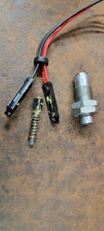
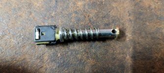
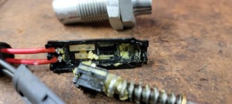
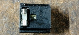
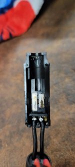
Curiosity got the better of me and I decided to disassemble the switch. I found the failure and got some new insight into the design of the wiring system. Turns out the switch simply opens or closes the red wires on one side, and the black wires on the other. When the brake pedal is released both are open due to the loss of contact on one of the slider pads. My switch failed due to arcing on one of the black contact pads as can be seen in the photos. This leads me to believe that the new superseded part was probably modified to add a stronger internal spring to the sliders' contacts. These ones feel pretty weak to me. The wiring diagram does not show these wires as two reds and two blacks; it just shows how they connect to the system harness at the connector. Black is ground for the lights. The red simply sends a discrete closed signal to the ECM to say that you've pressed the brake pedal. Brake pressure must be picked off from the VSS Antiskid module. These contacts are simply open or closed as depicted in the wiring diagram; no pressure signal is possible at this switch.



Last edited:
