Some additional information on my installation:
Throttle
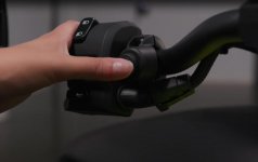
Under the left headlight cover are three black factory connectors: a 4-pin, 6-pin, and 12-pin (they may be in a different order, as I removed and replaced them from their mounts and I may not have replaced in the same order as original). The top connectors go to the handlebar controls, and the bottom halves to the wiring harness. The 6-pin connector is the throttle connection. The green with black stripe is the Throttle Sensor 1 and the green with yellow Throttle Sensor 2. Cut and connect these two at the wiring harness connector per the Rostra instructions. (if you get these wrong, the bike will enter Limp Home Mode as soon as you try engaging cruise.)
The gray connector is my added cruise control buttons - more on that next.

Cruise Control Switches
I ran 4 wires to the cruise control switches using the factory wire loom for the left switch pod. As stated, the On/Off switch is a push - on, push - off switch; the others momentary. Make the 4 wire connections to the cruise module per the Rostra wiring diagram. As explained, I added a connector so that the switch pod can be readily removed if necessary. As this added connector has no mounting point, I wrapped it in foam to keep it secure.

Brake
The brake connection can be made here, at this wire bundle that runs along the bottom of the frame to the rear of the bike. The Brake wire is white. There are two white wires; use either.

I solder then use Liquid Tape on these splice connections, then rewrap the bundle with black electrical tape. I ran this connection, along with the speed sensor wires, to the cruise module using wire loom (which I strongly recommend).

The Brake + connection on the cruise module can be simply wired to switched 12V power (aux power). It is a required connection for the module to function.
Speed pickup
Rostra supplies a mounting bracket for the speed pickup coil, but I used a piece if 1/8" sheet aluminum with a slot cut in it and a cable clamp.