• There were many reasons for the change of the site software, the biggest was security. The age of the old software also meant no server updates for certain programs. There are many benefits to the new software, one of the biggest is the mobile functionality. Ill fix up some stuff in the coming days, we'll also try to get some of the old addons back or the data imported back into the site like the garage. To create a thread or to reply with a post is basically the same as it was in the prior software. The default style of the site is light colored, but i temporarily added a darker colored style, to change you can find a link at the bottom of the site.

Where IS that front accessory pigtail?!

Big Mac

New member
I'd like to use the ignition-switched power available on the front accessory pigtail in order to switch my FZ1 fuseblock - but I can't find the pigtail!

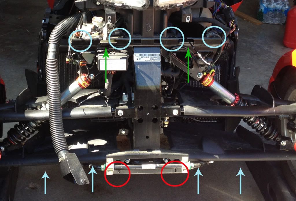
I've read that it is meant to be close to the hole which is pre-drilled in the frunk for the optional "DC12 Front Accessory Plug". Some posts say it is zip-tied to the frame near the top of the left shock absorber. But I suspect this is for the previous model (mine is a 2015 RT Ltd).

Is the pigtail (apparently a violet/yellow wire and a black wire, according to the Wiring Diagram) only visible after removing the whole frunk?
 
Here is a picture of a 2012 I found. You will not see the wire color. Look for the rubber boot. In the picture it is located near the upper right. Below the 2 right blue circles and to the right of the green arrow.

FirewallWhatIs.jpg
 
Behind the frunk

Hi Mac,

The pig tail you looking for may be best found by removing the battery cover. Its on the upper right as your looking at it. While your in there make sure the battery connetions are tight. That has caused a few problems noted on this forum.

Kaos
 
Last edited:
Thanks billybovine but, as I said, instructions for earlier models don't seem to apply (is that even an RT?).
 
Thanks Kaos - I've got the battery cover off and looked in great detail through the hole but cannot find anything obvious. thanks for the tip about the battery connections.
 
Thanks billybovine but, as I said, instructions for earlier models don't seem to apply (is that even an RT?).

The picture was to show you what your looking for. The real estate just looks a little different. On the 2015 there is a fuse box in that location but it will be near there. Unless, sorry I have to ask, do you have accessory plug and the wires are hooked up to that?
 
Found it!!!

I found another thread ("Badboy horn/ Stereo plug? / VKEY") with a photo showing its precise location and, critically, the note that the wires are inside a black rubber boot.

Armed with this new knowledge, I could see the boot hanging down behind the big red solenoid connector (next to the battery's positive terminal), and with a finger through the battery cut-out I was able to pivot the bottom of the boot forward until it just poked through the pre-cut hole for the accessory socket. The two correctly-coloured wires with spade connectors on the end then virtually fell out of the boot and into my hand!

I will post a photo in a moment........here it is.....

attachment.php
 

Attachments

  • IMG_2735.jpg
    IMG_2735.jpg
    41.5 KB · Views: 483
Last edited:
Excellent find.....do you happen to know what the maximum amps that this circuit is designed to carry and does any other item(s) on the bike share this??

Found it!!!

I found another thread ("Badboy horn/ Stereo plug? / VKEY") with a photo showing its precise location and, critically, the note that the wires are inside a black rubber boot.

Armed with this new knowledge, I could see the boot hanging down behind the big red solenoid connector (next to the battery's positive terminal), and with a finger through the battery cut-out I was able to pivot the bottom of the boot forward until it just poked through the pre-cut hole for the accessory socket. The two correctly-coloured wires with spade connectors on the end then virtually fell out of the boot and into my hand!

I will post a photo in a moment........here it is.....

attachment.php
 
Excellent find.....do you happen to know what the maximum amps that this circuit is designed to carry and does any other item(s) on the bike share this??
Both front and rear accessory plugs are on the same circuit. It's 18 ga wire fused at 5 amps, which is a higher amp than the chart on this page would indicate is safe. Other resources indicate 10 amp max capacity for 18 gauge wire. To be really safe keep it down to 5 amps.

https://www.bluesea.com/resources/1437
 
If both the front accessory pigtail and rear accessory plug are on the same circuit and you have moved the fuse so that you can charge your battery through the rear plug does that imply that the front circuit would now be live all the time? If so would this not defeat the ignition on signal that many are trying to use?
Correct. You have your choice, both accessory plugs hot all the time, or both hot only when the ignition is on. If you want the plugs to be hot all the time and you need a key on voltage source you have to tap into some other circuit. There are some circuits like the fog lights and grip heaters that are on the load shedding relay. They are hot only when the engine is running.
 
I have found another source of an ignition-switched signal.

On my 2015 RT Ltd, the outside section of the upper headlight assembly (called "high beams" here in the UK - I think they call them "fog-lights in the USA?) has a chrome dome about 30mm in diameter. My wiring diagram labels them as optional "Day Lights", and you could apparently buy something to fit in there ("5-LED front headlamp lighting accent") though I'm told it is discontinued and/or unsuitable for post-2013 models?

Anyway, the wiring for it is already in place, in the form of a blanked-off 2-pin Superseal Connector containing an orange and a black wire - sitting minding its own business right behind each headlight assembly. Black is ground, of course, and the orange comes from fuse F1 via the ignition switch - so I don't think it needs the engine running to be hot (as it is not in the load-shedding circuit).

You can actually access the connector without removing the headlight (though that in itself is fairly easy), as it can be seen through a hole below the mirror. In the photos attached, I have reached in with my little finger and teased it out of the hole slightly.

attachment.php


attachment.php
 

Attachments

  • IMG_2798a.jpg
    IMG_2798a.jpg
    47 KB · Views: 165
  • IMG_2799a.jpg
    IMG_2799a.jpg
    53 KB · Views: 170
Back
Top