• There were many reasons for the change of the site software, the biggest was security. The age of the old software also meant no server updates for certain programs. There are many benefits to the new software, one of the biggest is the mobile functionality. Ill fix up some stuff in the coming days, we'll also try to get some of the old addons back or the data imported back into the site like the garage. To create a thread or to reply with a post is basically the same as it was in the prior software. The default style of the site is light colored, but i temporarily added a darker colored style, to change you can find a link at the bottom of the site.

Electronic cruise control install

Hey @Rykerrally, thanks for posting this. If I end up getting a Ryker, I want to do this.

A search for 250-3472 on the site produced no results. Could the number of that part have changed?
 
Switch harness

Some additional information on my installation:

Throttle

Under the left headlight cover are three black factory connectors: a 4-pin, 6-pin, and 12-pin (they may be in a different order, as I removed and replaced them from their mounts and I may not have replaced in the same order as original). The top connectors go to the handlebar controls, and the bottom halves to the wiring harness. The 6-pin connector is the throttle connection. The green with black stripe is the Throttle Sensor 1 and the green with yellow Throttle Sensor 2. Cut and connect these two at the wiring harness connector per the Rostra instructions. (if you get these wrong, the bike will enter Limp Home Mode as soon as you try engaging cruise.)
The gray connector is my added cruise control buttons - more on that next.

View attachment 191508

Cruise Control Switches

I ran 4 wires to the cruise control switches using the factory wire loom for the left switch pod. As stated, the On/Off switch is a push - on, push - off switch; the others momentary. Make the 4 wire connections to the cruise module per the Rostra wiring diagram. As explained, I added a connector so that the switch pod can be readily removed if necessary. As this added connector has no mounting point, I wrapped it in foam to keep it secure.

View attachment 191507

Brake

The brake connection can be made here, at this wire bundle that runs along the bottom of the frame to the rear of the bike. The Brake wire is white. There are two white wires; use either.

View attachment 191509

I solder then use Liquid Tape on these splice connections, then rewrap the bundle with black electrical tape. I ran this connection, along with the speed sensor wires, to the cruise module using wire loom (which I strongly recommend).

View attachment 191510

The Brake + connection on the cruise module can be simply wired to switched 12V power (aux power). It is a required connection for the module to function.

Speed pickup

Rostra supplies a mounting bracket for the speed pickup coil, but I used a piece if 1/8" sheet aluminum with a slot cut in it and a cable clamp.

View attachment 191511


Where do you find the switch harness? There is none in the package 250-1882 I bought, even no connector? Does it come with the 250-3593 you bought (and don't use)?
 
Last edited by a moderator:
Where do you find the switch harness? There is none in the package 250-1882 I bought, even no connector? Does it come with the 250-3593 you bought (and don't use)?

There is no switch harness, you pull your own wires to the switches, and solder them to the switches themselves, unless you are referring to the cruise switches you pick when you buy the package? Then you will have that 'plug' at the module itself then just add your own wiring and pull it to wherever you want to mount your own switches.

EDIT: Had to go back and find my order, I picked the 250-3742 with the kit (250-1882), and just used the plug at the module, cut the wiring short, and ran my own wiring up to the switches
 
Last edited by a moderator:
Perfect after 1 year. Been through several rainstorms, no issues.

I put this writeup with more detail together a while back:
https://drive.google.com/file/d/10Mz3GH-D2DI3h-jZ10Kz_TmsMTooGYde/view?usp=sharing

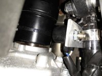
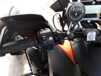
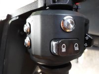
Thank you very much for sharing this memento; I got a lot of inspiration from it; I copied the installation of the speed sensor and the switches, I just moved the RES/Accel switch next to the on/off switch; it’s a little more ergonomic ... for my hands (see photos) and a little easier to install I think.
20230503_161800.jpg

20230503_162037.jpg

20230503_161638.jpg
 
Last edited:
Back
Top