• There were many reasons for the change of the site software, the biggest was security. The age of the old software also meant no server updates for certain programs. There are many benefits to the new software, one of the biggest is the mobile functionality. Ill fix up some stuff in the coming days, we'll also try to get some of the old addons back or the data imported back into the site like the garage. To create a thread or to reply with a post is basically the same as it was in the prior software. The default style of the site is light colored, but i temporarily added a darker colored style, to change you can find a link at the bottom of the site.

clock install

Larry t

New member
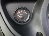
I want to replace fuel gague with digital clock, does anyone know which wire is power and which is light in multipin connector? don't want to hook up to the fuel sender wire by accident:banghead:

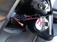
I disassembled and it was self explanatory but had to get constant power from main harness also, thanks for replys
 
Last edited:
Each gauge has 3 wires. I am sorry I do not remember the colors fully.

As I recall the white wire is the sending wiring.

The other 2 wires are power (ground and 12V). Orange as I recall is +12v and I forget the other color.
But understand, the 12V power wire is "switched" and that means when the key is off, there is no power. So if your clock requires always on 12V, you will need to get that from somewhere else and not the gauge wires.

Again a volt meter is your friend here to be sure. But you can also use a 12V light bulb if you do not have a meter.

Bob
 
Actually after reviewing an old video I made, I am incorrect in what I say above.

There are 4 wires in total.

3 are on that triangular connector. Then there is a stab on connector. This runs the light bulb in the gauge.
So the stab on connector is a "switched" 12V and is made to power bulbs in gauges.
On the triangular 3 prong connector there are 3 wires
Sense signal (S label on the gauge)
Ground - Center pin on the triangular 3 prong.
12V (I label on the gauge). But this 12V is also switched and is of low amperage. I would not connect anything to this 12V as it comes through the cluster!

Bottom line if your clock needs always on 12V you will need to get it from somewhere else. If it does not need always on 12V, then use the stab on 12V connector and ground from the 3 prong (center pin on the triangular plug). The stab on 12V connector does not go through the cluster and can handle more amp draw.

Here is a old video I did and at about the 4 minute mark I explain the connections.

Hope this helps.


Bob
 
Last edited:
Clock

Yep, just fitted an analogue clock this weekend buy using the +/- to the light on the gauge. The clock came with a button so that you can quickly set the time once the power is switched back on. I didn't want anything running when the bike is sitting idle. Used a volt meter to identify the polarity, but now I have to change the temp gauge because that wont work by it's self, :sour:
 
Last edited:
Yep, just fitted an analogue clock this weekend buy using the +/- to the light on the gauge. The clock came with a button so that you can quickly set the time once the power is switched back on. I didn't want anything running when the bike is sitting idle. Used a volt meter to identify the polarity, but now I have to change the temp gauge because that wont work by it's self, :sour:

found that out, installed volt meter to take its place
 
While I have a RAM mount where the other analog gauge would go, which is for my 775T GPS (which by the way LOVE that location) now that I have a iPhone 6 with a better GPS capability than any Garmin to date, I am thinking of getting rid of the RAM mount and putting a nice gauge there.

So what clock did you get?

Bob
 
Mounting question..

Not to hijack the thread here but how did you mount the gauges to the panel? In my case the mounting bracket is deeper than then new instrument so immediate logic suggests some type of adhesive. Nonetheless I figured I might ask for a little public opinion before doing anything permanent.

I have gone with the Volt/G-meter (Space filler) for my selection.. Just deciding how to best attach them to the panel facia.
 
In my case the new volt meter mounting bracket worked fine. Similar to the stock gauges.

You may want to see if you can fabricate something like the stock bracket.

Can you show a pic of this gauge and it's mounting?

Bob
 
clocks

Well I'm waiting for this volt meter to turn up, but if it's like the clock it should be a piece of cake. they fit in quite easy no issues at all.


this is the Clock I fitted, very simple installation and the button on the right only takes seconds to adjust to the correct time once you've put the key in the ignition.

At first I bought a digital Volt meter because another chap had used one and posted it on Youtube, but it didn't look right for me. Then when I checked my dash I noticed that the outer ring was chrome on the original fuel and temp, so I changed to the one's shown above. I think as long as you use a 52mm clock you should be ok.
 
Last edited:
clock

While I have a RAM mount where the other analog gauge would go, which is for my 775T GPS (which by the way LOVE that location) now that I have a iPhone 6 with a better GPS capability than any Garmin to date, I am thinking of getting rid of the RAM mount and putting a nice gauge there.

So what clock did you get?

Bob

found correct size on e-bay, made sure it had external adjustment is digital red #'s goes totally dark when key off doesn't draw enough to run battery down for my use
 
Voltmeter replaces Fuel Gauge

attachment.php


This is a voltmeter installed where the Fuel Gauge would have been. 2011 RT.
 

Attachments

  • IMG_0109.jpg
    IMG_0109.jpg
    67.9 KB · Views: 445
Connections

attachment.php


This is a voltmeter installed where the Fuel Gauge would have been. 2011 RT.
How are those connections working out for you? I didn't connect mine up like that. I used the centre cable out of the block of 3 but then I used the loose red cable to give me the 12 volts. You seem to be using the signal cable going to the instrument. When I tested it the centre and the loose red went to the light bulb of the gauge. But hey ho! if it works :clap:. The centre cable and the red cable switch on and off with the lights.
 
Last edited:
Digital gauge

This is the volt gauge I put in.


Bob
Thanks Bob, I bought this this gauge as well, after seeing your clip. But I also bought an analogue one aswell just in case I didnt like it. I noticed that the instrument on the other side of your dash had a black surround which makes the two of them blend in as a pair. They look nice together. :clap:
 
How are those connections working out for you? I didn't connect mine up like that. I used the centre cable out of the block of 3 but then I used the loose red cable to give me the 12 volts. You seem to be using the signal cable going to the instrument. When I tested it the centre and the loose red went to the light bulb of the gauge. But hey ho! if it works :clap:. The centre cable and the red cable switch on and off with the lights.

The centre cable is ground (-ive) and the red is switched +12V. The unused position is the signal cable. Been working now for 4 seasons and the voltmeter has never had an issue.


attachment.php
 

Attachments

  • IMG-20130817-00066.jpg
    IMG-20130817-00066.jpg
    71.5 KB · Views: 421
Cables

The centre cable is ground (-ive) and the red is switched +12V. The unused position is the signal cable. Been working now for 4 seasons and the voltmeter has never had an issue.


attachment.php
Cool but just so I get this right, the cable with the female spade connector (I take it) is the + 12v switch that is connected to the relay that brings the lights on. The centre cable of the 3 is the - or ground cable, and so I always thought the outer 2 cables of the 3 were the instrument cables.?
 
I would not use the 12V coming out of the 3 prong connector. That goes through the cluster! The single red spade connector wire does not go through the cluster.

Bob
 
Dashing set up

I would not use the 12V coming out of the 3 prong connector. That goes through the cluster! The single red spade connector wire does not go through the cluster.

Bob
So I've now fitted both replacement gauges, wanted to keep it simple with no mess. Installation took about 1 hour. First pic is with the ignition key in the on position and the voltage showing is the output from the battery. Just one word of warning, when your looking for a replacement gauge don't buy a long body replacement gauge (they don't fit snug). The volt meter shown here was not the original intended gauge. The first one I bought had a really long body and it didn't fit so back to ebay and found this baby which is the same as the one shown on the youtube clip.


This next pic shows the charging voltage which is really handy,

 
Last edited:
Cambello
Where did you get the clock?? I would like to replace my unused gas gauge with the same digital one!
Thanks
 
Here's an idea....

Why don't you take an old G-Shock wrist watch and just strap it to your handle bar? It's always working, waterproof, no wiring, and should you need to replace it, it takes seconds to swap out... No volt meter required.:thumbup:
 
Back
Top