This should work on any F3 model. Attached are: photos of the finished installation and the wiring schematic. This is not a step-by-step on running the wires as the project requires the doer to understand electronics and electricity, beyond the scope of the write up.
In the end I have a live battery tender port, relay on-with-the-engine connections for my GPS, multiple USB ports, and heated gear socket. The box and components were purchased off Amazon; they are splash and rain proof sockets, mounted down and out of the way from rain and wind. The box is held in place via adhesive backed Velcro(tm) to allow access to the air filter and other service needs under the panel.
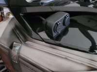
The first image is of the finished installation, where the Auxiliary Power Box was attached to the Left Service Cover; it could also be installed on the right side, although the left side has a shorter battery run.
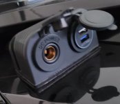
Second image is simply showing the ports that I chose to enclose in the box: a Hella DIN socket and a dual USB port. You may want a different configuration. The heated gear socket was routed to the left handlebar area and the GPS connection is under the panel.
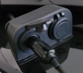
Third image shows the battery tender plugged into the Hella DIN socket. Get done with a ride, open the cover and insert the plug. There should be no parasitic drain from this socket as it has no associated lighting or meter.
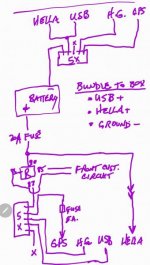
The last image is the wiring schematic. The circuit is protected by a 20A fuse, after which it splits to maintain the hot connection to the Hella DIN port and connects to the 20A relay. Find a wire that goes live after the engine is running to turn on the relay. Three wires were run from the battery area, under the Frunk Tub, to the area under the service cover enclosed in a flexible wire loom: a common ground wire, the hot wire to DIN socket, and the hot wire from the relay for the other connections. All wire-to-wire connections were made with Wago Lever-Nuts, keeping it simple and re-enterable, if needed.
In the end I have a live battery tender port, relay on-with-the-engine connections for my GPS, multiple USB ports, and heated gear socket. The box and components were purchased off Amazon; they are splash and rain proof sockets, mounted down and out of the way from rain and wind. The box is held in place via adhesive backed Velcro(tm) to allow access to the air filter and other service needs under the panel.
The first image is of the finished installation, where the Auxiliary Power Box was attached to the Left Service Cover; it could also be installed on the right side, although the left side has a shorter battery run.
Second image is simply showing the ports that I chose to enclose in the box: a Hella DIN socket and a dual USB port. You may want a different configuration. The heated gear socket was routed to the left handlebar area and the GPS connection is under the panel.
Third image shows the battery tender plugged into the Hella DIN socket. Get done with a ride, open the cover and insert the plug. There should be no parasitic drain from this socket as it has no associated lighting or meter.
The last image is the wiring schematic. The circuit is protected by a 20A fuse, after which it splits to maintain the hot connection to the Hella DIN port and connects to the 20A relay. Find a wire that goes live after the engine is running to turn on the relay. Three wires were run from the battery area, under the Frunk Tub, to the area under the service cover enclosed in a flexible wire loom: a common ground wire, the hot wire to DIN socket, and the hot wire from the relay for the other connections. All wire-to-wire connections were made with Wago Lever-Nuts, keeping it simple and re-enterable, if needed.