• There were many reasons for the change of the site software, the biggest was security. The age of the old software also meant no server updates for certain programs. There are many benefits to the new software, one of the biggest is the mobile functionality. Ill fix up some stuff in the coming days, we'll also try to get some of the old addons back or the data imported back into the site like the garage. To create a thread or to reply with a post is basically the same as it was in the prior software. The default style of the site is light colored, but i temporarily added a darker colored style, to change you can find a link at the bottom of the site.

Shans - Portable CB set up

My wife has recently bought a Spyder, so I am thinking about how to hook her up with CB so she can talk to me on my GoldWing. I will no doubt create a system for her using a Midland CB and an Autocom, as I have on my Wing.

It would of course be nice to use the bike's built-in PTT switch, and from reading these threads on here it seems that I will face the same problem in using the PTT wiring as I did on the Wing - i.e. it is part of an addressable switch system and so the existing wires cannot easily be used in the way you might expect.

However, my solution on the Wing was to unsolder the wires from the PTT switch and run a new twisted pair down the handlebars and to my CB unit. Has anyone tried that with the Spyder? Is it easy to get to the back of the PTT switch?

Other Wingers have simply added a momentary toggle switch - maybe in a tiny box - and stuck it somewhere convenient for the left index finger, running wires from that down the handlebars. Presumably some Spyder owners have tried that method too?

Hi, KA2PFL and N2GUU here.
This is the Ham radio on our 2015 RTL. The Radio is installed in the trunk (so I do not fiddle while Spydering down the road). :trike:


attachment.php


The antenna is mounted here with a metal plate under it for strength.
attachment.php


It was installed above the Chicken Band hole so it would line up with the AM/FM antenna like this. I took the photo at an angle, but side on both antennas are in line.

attachment.php


The radio is connected to a Sena SR10 mounted here. I wired the PTT to the Spyders PTT switch on the handlebar.

attachment.php


attachment.php


It works great, but kind of missing the 30 watts of a mobile dual bander.

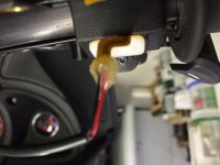
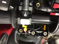
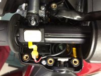
You can get to the PTT button, but you will have to cut the flex circuit and carefully solder to the plastic based flex circuit without melting it. If you want I can post a picture of the switch and flex circuit.
 
Roger Wendal had posted a picture of how he got to the PTT switch. I am looking for it. I found it once before.

Bob
 
We would sure like to see the pic of the ptt switch and circuit! :bowdown:

Here you go.

attachment.php
attachment.php
attachment.php


The flex circuit was snipped in half to isolate it from the spyders electronics. The red and black wire was soldered to the flex circuit after carefully scraping the plastic layer off one side. The blob you see is 5 minute epoxy to prevent the soldered wires from breaking off. I epoxied one side, let it cure, then epoxied the other side. You can see the notch I cut into the plastic (near where the wires are coiled up) so the wire will not get pinched when the switch assembly is screwed back together.

The wires are routed the same way as the spyders. Mine run to the trunk where the ham gear is, yours will run to the handle bar for your CB radio. The hardest part of the whole job is soldering to the flex circuit. The traces are small and close together. And you need a temperature controlled soldering iron so you do not melt the flex circuit. If you have soldered before, you should not have an issue. Leave the flex circuit long, so if you screw it up you can cut that piece off and try again. I got it right on the first shot but I have been a electronics tech for 45 years :)
 

Attachments

  • IMG_0113.jpg
    IMG_0113.jpg
    40.3 KB · Views: 472
  • IMG_0115.jpg
    IMG_0115.jpg
    59.2 KB · Views: 473
  • IMG_0116.jpg
    IMG_0116.jpg
    59.1 KB · Views: 473
Many thanks, Louie/SpyderCruiser - that's all very useful. How easy is it to get at the PTT switch - just a couple of screws?
 
Many thanks, Louie/SpyderCruiser - that's all very useful. How easy is it to get at the PTT switch - just a couple of screws?

Your quite welcome :D

Yes, very easy. Screws are easily seen from the front of the switch cluster. The switch is a membrane switch glued on. I chose not to remove it (it might tear) and cut the flex circuit to gain access to the switch connections like the photo's show.
 
Flex circuit goes where to?

Hi all,
appreciate the DYI efforts to get to the Spyder PTT circuit.
Since I used to be a wire harness designer in the auto industry. Every wire/circuit has 2 ends. So where do the circuits for the flex from the PTT go to next? another connector? splice? If a connector somewhere then a harness to break out to a SR10 or other input for PTT should be fairly easy.
I wish I was still able to do that sort of work but not able anymore.

Andy

Hi Andy,
I wish it was that easy. The flex circuit goes directly to a can bus chip in the control housing, the PTT leads do not exit the control as such. They are placed as a digital signal on the can bus. This why the flex must be cut inside the control and connected to external wiring.
 
The flex circuit goes directly to a can bus chip in the control housing, the PTT leads do not exit the control as such.
That's what I feared.

Did you find it easy to run new wires down the handlebars - under the cover presumably? Do you have any photos of that, or the loop I guess you made near the handlebar pivot point?
 
That's what I feared.

Did you find it easy to run new wires down the handlebars - under the cover presumably? Do you have any photos of that, or the loop I guess you made near the handlebar pivot point?


Sorry, did not take photo's of that. The wire is wire tied with the bundle of cables from the handlebars. It was very easy to run the wires under the covers.
 
Hi Andy,
I wish it was that easy. The flex circuit goes directly to a can bus chip in the control housing, the PTT leads do not exit the control as such. They are placed as a digital signal on the can bus. This why the flex must be cut inside the control and connected to external wiring.

Thanks SpyderCruiser for your efforts; no doubt this is probably the purest signal for the PTT which can be tapped into from the flex circuit.

So it sounds like the CAN-bus should have a signal (on or off; digital in a sense) for the PTT button. However I would be skeptical to think that this signal is time shared like in a computer CPU bus. If memory serves me correctly; Mobile 2 way radios (commercial, ham, and public) typically have 2 inputs related to this topic of PTT: ground and PTT input signal where the voltage is applied.
So if the goal is to get the PTT signal coming from a wire harness connector. I guess maybe the better question is: well how does the BRP CB radio module get the PTT signal from the CAN-bus which is fed(connected) directly or indirectly by a wire harness(es) it seems? So we can duplicate with an aftermarket 2 way radio.

Food for thought. (73 N9UFI for ham operators)

Andy
What little I've read up on CAN BUS it is a serial communication system over one pair of wires, so yes, it is much the same as USB.

I'm quite sure it is time shared as it is on the bus with the radio, cluster, ECM, VSS, and what all. The chip in the left handlebar is the communicating processor for several items on the left switch, plus the right switch. The right switch feeds to the left switch which does the CAN BUS communicating. The radio picks up the PTT signal and puts one of the pins in the radio to CB connector high. See Bob's comment in post #13 above.

I haven't asked Bob yet which pin goes high but I plan to. I will be removing my CB to have it repaired this winter so that will a good time to do some testing. The questions that remain, and maybe Bob has the answer to the first one, is will the radio capture the PTT signal and take the pin high in the absence of the BRP CB, and how is the best way to capture the high signal to use it to trigger the transmit in the portable CB? There is no easy or practical way to directly capture the PTT signal other than maybe building another processor to hang onto the CAN BUS to capture the PTT code. But why do that when the radio already is doing that?

Thanks for the explanation, could not have explained it any better. When I made my harness for the Sena and had the radio accessible, I connected a VOM to every pin on the radio. Tried it connected to ground and to + 12V. Was looking for a high or low to ground or B+ while my Wife was operating the PTT. Could not locate a pin related to the PTT. I suspect Bob located an isolated pair of connections I missed.

This is why I chose to cut the flex and add the external wiring.
 
The radio does not "pass through" the can-buss messages to the ENT harness to operate the XM and CB.
The radio receives messages and if they are destine for the CB or XM radio, it manages them and translates them. So it's not a pass through system. The radio is the master for the CB and XM on the ENT harness.
So in other words, when PTT is pressed the radio gets this CAN message and then creates a new message for the CB (and XM since it mutes that).

I have the pin out information which with some study (it's not obvious you have to cross ref the pins in the documentation I have) you can track down the output CAN high and low pins from the radios RD0-2 connector. These are what you will see toggle when PTT is pressed. They are not a logic TTL level high/low but you can see a signal spike as the message is being sent and again when the PTT is released.

To make this work would require a little but of a circuit design. Opto-isolators so you don't mess up the can-buss (but this may not be needed). A 555 timer setup watching the signal spike which then triggers a relay or solid state switch (I would go with a relay myself) to toggle the push to talk cable input of the Midland CB. It sounds heavy duty but shouldn't be really.
I have just not had time to work on this more recently... Wish I was retired or it would be done by now ;)

PM me if you want me to send you the pinout info.


Bob
 
Last edited:
The radio does not "pass through" the can-buss messages to the ENT harness to operate the XM and CB.
The radio receives messages and if they are destine for the CB or XM radio, it manages them and translates them. So it's not a pass through system. The radio is the master for the CB and XM on the ENT harness.
So in other words, when PTT is pressed the radio gets this CAN message and then creates a new message for the CB (and XM since it mutes that).

I have the pin out information which with some study (it's not obvious you have to cross ref the pins in the documentation I have) you can track down the output CAN high and low pins from the radios RD0-2 connector. These are what you will see toggle when PTT is pressed. They are not a logic TTL level high/low but you can see a signal spike as the message is being sent and again when the PTT is released.

To make this work would require a little but of a circuit design. Opto-isolators so you don't mess up the can-buss (but this may not be needed). A 555 timer setup watching the signal spike which then triggers a relay or solid state switch (I would go with a relay myself) to toggle the push to talk cable input of the Midland CB. It sounds heavy duty but shouldn't be really.
I have just not had time to work on this more recently... Wish I was retired or it would be done by now ;)

PM me if you want me to send you the pinout info.


Bob

Thanks Bob. That is why I could not find it. I was looking for a logic high or low. So you are saying that the radio sends a digital "word" on the bus to the CB. You mentioned a spike upon keying and a spike upon unkeying. Bet that it is 2 different digital "words".

Rather then going with a 555 timer, may need to use a small microprocessor to decode the digital "word". Using the toggle function of the 555 there can be a time where there can be confusion and the PTT could be stuck. That is why I believe you see a spike on PTT on and another when you release the PTT. 2 Digital "words", "PTT ON AND HOLD" and "PTT RELEASE" are being sent to the CB I would guess.

This is correct and I was going to have a PTT time out on the 555 so if it "got stuck" after say 2 minutes it would reset. Not perfect but is a fall out timer should that happen. But yes the two spikes are the "words" being send for PTT ON and PTT OFF. Well that's my theory anyway as is yours :)

So here is the deal on the CAN-buss. You can find info here where people have tried to decode it from about 2 years ago. You can use a standard ODB-II device like those used with cars and it will see the Spyder buss. However it is not using standard protocol. BRP in their infinite wisdom decided to modify the protocol to make it proprietary. Thus to actually figure out the messages and use a PAL or programmable processor to read it, you will need a ODB-II development / debug system. There was a guy here about 2 years ago that started trying to decode the buss messages and did make a tiny bit of progress. So if someone has a debug system and can determine the messages for PTT, then yes the best way would be to use a programmable processor to actually use the real can-buss messages.

Alas, that is a little farther than I am willing to go and shell out the bucks for a ODB-II development system.

Bob
 
Last edited:
One more comment. The entire audio system (radio, CB, XM) is made by RadioSound corp not by BRP.

This is why the can-buss from the radio to the CB/XM is not the same as the can-buss as on the Spyder.
Consider it a sub-net if you will.

So when a motorcycle manufacturer wants to use the RadioSound system, they only need to implement the radio can-buss commands to the radio. They do not have to also integrate the CB/XM as the radio handles that subnet. The motorcycle manufacturer thus gets a set of can-buss commands the radio understands and the radio then sends commands to the CB/XM.

So, with that said, it might be easier to decode the radio sub-net than the hacked up can-buss on the spyder itself.

Just a thought... But you will still need a ODB-II development system I think.

Bob
 
I for one appreciate all the work and wisdom from those here figuring all this out.
Things sure have changed since I did wiring on big trucks and earned my amateur radio license decades ago. It seems everything is digital now.

Thanks again for all the effort.

Andy (N9UFI)

P.S. I'll keep monitoring to see if you all come up with another solution for the PTT.
 
Back
Top