• There were many reasons for the change of the site software, the biggest was security. The age of the old software also meant no server updates for certain programs. There are many benefits to the new software, one of the biggest is the mobile functionality. Ill fix up some stuff in the coming days, we'll also try to get some of the old addons back or the data imported back into the site like the garage. To create a thread or to reply with a post is basically the same as it was in the prior software. The default style of the site is light colored, but i temporarily added a darker colored style, to change you can find a link at the bottom of the site.

Spyder surgery - one less thing to remove for servicing!

Did you happen to see/feel the opening that PMK mentioned.\??? I couldn't find anything other opening further down the intake pipe. BUT maybe right after the part I heated there was a hole that I may close to use the openings I made to have a straight entrance without any turbulence. Just a little something I've learned about ram air intakes.

Lew L

No, I haven't tried poking around in there yet. I think I'll wait until I remove the frunk this summer. I have some maintenance items to take care of (various filters and maybe spark plugs) that will be easier without the frunk in the way I think. Also, a BajaRon sway bar, the new one.
 
Lew have you ever had the frunk off ???? .... you can see the entire plastic intake ..... Mike

Yes I have but I was doing the DESS R&R. I think the opening that PMK is talking about is on the bottom of the intake tube.

I'll bet you have that piece lying about after your intake changes????
 
Yes I have but I was doing the DESS R&R. I think the opening that PMK is talking about is on the bottom of the intake tube.

I'll bet you have that piece lying about after your intake changes????

:roflblack::roflblack::roflblack: ..... you bet I rarely throw anything away :yes: .... If you tip the frunk forward and stand it on it's nose ( with help ) the blk intake is attached to the left side ..... good luck ... Mike :thumbup:
 
Did you happen to see/feel the opening that PMK mentioned.\??? I couldn't find anything other opening further down the intake pipe. BUT maybe right after the part I heated there was a hole that I may close to use the openings I made to have a straight entrance without any turbulence. Just a little something I've learned about ram air intakes.

Lew L

Lew since I actually removed the entire piece there ARE only TWO OPENINGS , the END that connects to the airbox ( rubber elbow ) and the smaller " slit " at the bottom .... I think PMK was referring to way the INTAKE piece is shaped .... relatively small at both ends, but the middle bulges out quite a bit ..... Mike :thumbup:
 
Last edited by a moderator:
Lew since I actually removed the entire piece there ARE only TWO OPENINGS , the END that connects to the airbox ( rubber elbow ) and the smaller " slit " at the bottom .... I think PMK was referring to way the INTAKE piece is shaped .... relatively small at both ends, but the middle bulges out quite a bit ..... Mike :thumbup:

Said "bulge" will cause a pressure drop in a ram air system. I'm not saying that what I've done is " ram Air" by any stretch, but what I have done will feed the low pressure in the intake tube better.
 
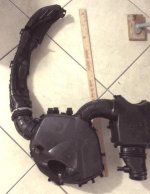
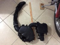
This is the intake ducting and airboxes from a 2014 RTS. At the forward end, just aft of what Lew cut away, is a huge air inlet. Forward of the radiator, aft of the front edge.

The complete induction system prior to the throttle body is in one photo. Note the large unrestricted opening at the forward end of the duct.

The second photo, unfortunately does not show the entire length of the air duct. At the right side end of the photo, the inlet is visible.
 

Attachments

  • 097F5E7D-C8D6-42AE-A1CC-6899A82E0525.jpg
    097F5E7D-C8D6-42AE-A1CC-6899A82E0525.jpg
    48.8 KB · Views: 35
  • F593012D-DA79-483D-9905-74A563A5DA4E.jpg
    F593012D-DA79-483D-9905-74A563A5DA4E.jpg
    67.4 KB · Views: 32
.

I've looked with an endoscope to try to find this opening and I can't find it:helpsmilie:......

PMK, Does the opening face down?? Where does it draw intake air from?? I know it's not forward and above the radiator that can be seen from the front. Is the opening to the side?? Upwards???

Help----------My curiosity is getting the better of me.

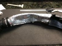
Lew, I think in the first picture the opening is visible at the top of the image (hard to see because it's black on black). In the second picture, which seems to be after the reflective heat film is applied, the opening is clearly visible to the right. The 'bulge' is seen as a concave portion of the tube.

20220620_222815.jpg

I think what PMK is saying is that even with the constriction in the tube there is adequate air flow and the existing duct inlet brings in plenty of cold air. But, the tube passing thru the engine compartment picks up too much heat energy which is why he wrapped it in foil and why Can-Am subsequently made changes to the way intake air is routed to the engine to mitigate the heat gain.
 
Last edited:
Lew, I think in the first picture the opening is visible at the top of the image (hard to see because it's black on black). In the second picture, which seems to be after the reflective heat film is applied, the opening is clearly visible to the right. The 'bulge' is seen as a concave portion of the tube.

View attachment 196979

I think what PMK is saying is that even with the constriction in the tube there is adequate air flow and the existing duct inlet brings in plenty of cold air. But, the tube passing thru the engine compartment picks up too much heat energy which is why he wrapped it in foil and why Can-Am subsequently made changes to the way intake air is routed to the engine to mitigate the heat gain.

Correct.

When assembled, the actual air inlet is forward of the radiator, at a height similar to the top of the radiator. I posted the photo of all the air inlet components as they are situated in the Spyder. You may need to zoom in on the photo, and yes it is black making details less apparent.

While Mike has added a scoop to bring in cool air, he also removed a large area of duct that becomes heat soaked. Doing this no doubt reduced heat. Had Mike gone a step further, he might have considered adding his elbow scoop on the Spyders right side. Doing this he could have removed all the plastic ducts and airboxes. A simple filter with a shroud would feed directly to the throttle body. Downside could be intake noise though.

Hopefully the heat mitigation material I am installing will lower intakes temps closer to ambient. Seeing temps of the air feeding the engine, being 30*f above ambient is not conducive to making power or an efficient engine.
 
.

I've looked with an endoscope to try to find this opening and I can't find it:helpsmilie:......

PMK, Does the opening face down?? Where does it draw intake air from?? I know it's not forward and above the radiator that can be seen from the front. Is the opening to the side?? Upwards???

Help----------My curiosity is getting the better of me.


The opening is behind where you chopped up the plastic. The item you heated and distorted partially feeds the actual air intake. Once you disassemble and remove the duct, it will be apparent how well the inlet was designed. It uses positive pressure inside the radiator nacelle, but forward of the radiator exhaust heated air, to feed the engine air.

The air inlet location on the 2014 to 2019 is superior to the 2020 and later RT series. These 2014 / 2019 models have a true positive pressure inlet with adequate duct cross section for the size of the throttle body. Heat is what kills the design.

The 2020 and after use essentially the same primary airbox, but Can Am omitted the inlet duct. Therefore a 2020 and after draws intake air from under the bodywork. Simple aerodynamics would suggest this is a low pressure area, not ideal for positive induction air feed to the airbox. Can Am moved the radiators outboard of the bodywork in 2020. An obvious attempt to cool the underside of the bodywork. Because of this, adding an elbow scoop as Mike did, may induce better air entry , but also may introduce heated air.

From an efficiency standpoint, the more tightly designed body shape of the pre 2020 Spyder RT, and the smaller overall size, plus the more compact radiator placement should make the 2014 / 2019 better aerodynamically and therefore more efficient. What kills it though is heat being added to the cold air induction, robbing a lot of available power. The heat reduces air density. Less dense air makes less power. You can modify the oem inlet to be twice as large, the location is not going to add any pressure or flow beyond what oem has. Even with that, once within the system, that trapped air is quickly heated.

If the oem primary airbox were to have an exhaust added, so cool air could constantly flow while moving, vs being dead ended (except for consumed air), this may lower airbox and air duct temp somewhat. This airbox exhaust would need to exit at a know point that would not allow heated air from under the bodywork to enter the airbox.

Thank you for the detailed description of the opening. I'll continue to search for it. Your photos make the opening plain but with all the tupperware in place I still can't find this large opening. I have "exposed" the end of the inlet tube into the large opening I created above the nacelle ( divided from) the radiator.
Thanks again---
 
Last edited by a moderator:
Back
Top