Spyder Hawk
Member
Well there is no power to the supplied switch. The power I was getting yesterday must have been from the bike only. Could the relay be bad?

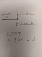
Billybovine suggested that the BRP switch might be a single pole and the one that came with the unit might be a double. Is there a way to find out which is what? I was able to get the BRP switch to work but it only has one level of heat and the light is not on. I purposefully didn't connect it because I thought it may be the problem. I think there was to much power going to it when it is only for the light. Going to tap the parking light and see if that makes a difference.
That is part of the problem. The harness is all sealed up inside a thick black cover. You can't see where the wires go or what they connect to. The heating unit is a Hi / Low kind of thing so I assume that is where the relay comes in.
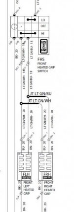
From what I can see it is a simple Red and Black coming from the pads. They go into the relay and are joined by a yellow wire. From my above pic starting at the top it goes...
3 blacks
1 red
1 yellow
1 red
But when they come out of the harness to the switch they are...
1 red
1 black
1 yellow
1 white
I wrote to the seller and asked for another harness being that I don't trust this one.


I hate that I am so helpless now. A few year ago this would not have been so difficult. Once again I would like to express my thanks to all of you. That being said here is a pic of the BRP switch in its working state, one heat setting only.
View attachment 182392
I wonder if the ground wire needs to be a chassis ground or does that matter? I read that the switch ground was for the switch light only. The ground for the heat pads is the battery ground I assume.
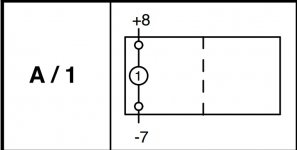
This pic is of the relay and I don't know what is going on in there. If the seller sends me another harness I can tear this one open and then we can see what is going on inside.
View attachment 182393
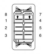
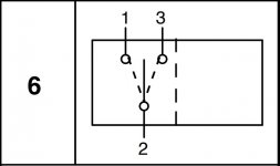
This is the supplied switch but I can't tell what is what.
View attachment 182394
I found one switch on Amazon but it is a spot as well. Which is what I have with the BRP switch I think. The didn't switches all have 7 pins.
There must be something going on in the harness because the white wire just comes out of nowhere. It's not on the relay so it must be coming out of the harness under all that bundled black mess. I assume that is where the diodes Billy mentioned might be.
I was able to get an old meter working but don't know what kind of numbers I am looking for. Would it help you all if I took readings from the switch?