billybovine
Active member
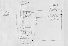
Perfect. That's very close. I am wondering which switch wire is constant power. I would assume it's the red. Then it is connected correctly by your pic and should work. But maybe it is not. Can you test that.
Do I possible need one of these? If there is no way to get what I have to work correctly.
View attachment 182399
I suppose that will require taking the harness apart.

In post 30 he says there are 3 blacks, two reds, and one yellow going to the relay. There is no way I can see how you can have Lo/Hi heat without using all 5 terminals of the relay. The wiring diagram I used to try to figure this out is in this installation instruction. It's for a similar kit but without the yellow switched wire. https://www.google.com/url?sa=t&rct...allation.pdf&usg=AOvVaw3fJ3eJ975-I7AWmvxTKYgf.You may have missed some of the things Spyder Hawk told us. The relay has only 4 wires going to it. Your diagram has 5. The yellow switched source wire goes to the relay. Not the switch.
WOW, lots of discussion on this one, that's great.There is also a 5th pin on the relay that is not connected to anything.
View attachment 182341
The one in the center.
WOW, lots of discussion on this one, that's great.
However, all this discussion and I did not see anyone address your concern about the pins on the relay.
Four of the pins will have numbers: 30, 85, 86, 87. The center pin will also have a number, and the number will tell you what it does. Is that center pin #87 or #87a?
In a typical wiring diagram, 85 or 86 will be the trigger for the relay, the other pin will be the ground. Pin #30 will be the power in and #87 is the switched power out.
If the center pin is #87, it is simply a second switched pin that comes on at the same time as the other one. Very handy when connecting something like fog lights or driving lights, you connect one light to each terminal. If the center pin is #87a, it will be ON when the #87 pin is OFF. Power from #30 will go to one or the other, but not both.
.
If it was intended, or sold as, having both high and low heat then I say they wired it wrong.I found this diagram but it uses all 5 posts of the relay I think. I wonder if they wired this one wrong.
View attachment 182426
WOW, lots of discussion on this one, that's great.
However, all this discussion and I did not see anyone address your concern about the pins on the relay.
Four of the pins will have numbers: 30, 85, 86, 87. The center pin will also have a number, and the number will tell you what it does. Is that center pin #87 or #87a?
In a typical wiring diagram, 85 or 86 will be the trigger for the relay, the other pin will be the ground. Pin #30 will be the power in and #87 is the switched power out.
If the center pin is #87, it is simply a second switched pin that comes on at the same time as the other one. Very handy when connecting something like fog lights or driving lights, you connect one light to each terminal. If the center pin is #87a, it will be ON when the #87 pin is OFF. Power from #30 will go to one or the other, but not both.
.
If it was intended, or sold as, having both high and low heat then I say they wired it wrong.
In post 30 he says there are 3 blacks, two reds, and one yellow going to the relay. There is no way I can see how you can have Lo/Hi heat without using all 5 terminals of the relay. The wiring diagram I used to try to figure this out is in this installation instruction. It's for a similar kit but without the yellow switched wire. https://www.google.com/url?sa=t&rct...allation.pdf&usg=AOvVaw3fJ3eJ975-I7AWmvxTKYgf.
I give up! I don't have any more time to work on this. As far as not staying on when the ignition is turned off I believe his kit is intended for auto use with main power coming from a switched source. He used the word illumination for the yellow wire which indicates that wire connects to the car lights so the switch will be illuminated at night. I'm sure the switch has internally wired LEDs to indicate when the heater is on.
