PinkRosePetal
New member
Hehe..I think you're off on a tangent! Pun intended! Consider the force required to rotate the tyre contact patch to a new position for steering to take place.Interesting, isn't it?
Happy new year!
Hehe..I think you're off on a tangent! Pun intended! Consider the force required to rotate the tyre contact patch to a new position for steering to take place.Interesting, isn't it?
In the curve the tire contact patch is not rotating with respect to the Spyder, but it is with respect to the center of the turn. In this case it is one of the components of the friction force pushing the Spyder to the center of the curve. In any case the force to turn the wheels to begin the turn is minuscule compared to the force required to push the Spyder to the center, I say.Hehe..I think you're off on a tangent! Pun intended! Consider the force required to rotate the tyre contact patch to a new position for steering to take place.
Happy new year!
If the lasers are parallel to the ground, a target placed in front of and square to the vehicle alignment centre, can be marked at the laser dots. If the target is then moved by the required toe distance (wheel rim diameter for me) then the difference between the dot spacing on the target equals the toe distance.
The main issue is to avoid that camber error
(try measuring the error in an extremely flat triangle that long and you'll suffer brain damage)
The above offsets apply as well to when using a machinist square to transfer the laser line to the floor. The machinist square must be leveled so that the edge of the scale is truly plumb.
What brand of lasers are you fellows using on your setups?
How do you mount it to send the beam forward and backward? From what I read in the instructions the only approved mounting position is for the beam to shine to the left. Do you just stick it to a plate with the magnets on the backside like Lindsay shows and then turn it upside down to shine to the right? Looking at laser levels on Amazon, Home Depot, etc., it looks like most all of them are intended to be used with beam shining to the left. None of the instructions I looked at show shining the beam to the right.I use Powersmith PLTL320. Has dot and line generator and magnetic base.
I take it then the lasers are not free floating inside the level, i.e., they are adjustable up/down with screws with respect to the magnetic base but not free to move as they would be in a self leveling laser. Those you would not want to use on their side, would you?• the beam shining to the left or right: I use lasers with magnets on the bottom so they get used on the standoffs (which have a flat steel plate like a pie-dish, parallel to the brake discs), and are lying on their sides, so laser up-down inaccuracy becomes side-to-side inaccuracy. Calibrating the lasers ignores side-to-side because that won’t matter for alignment purposes. But they are carefully calibrated for up-down, relative to the magnetic base (I use the entire length of my house, and both beams hitting the far wall exactly alongside each other). Just attach the lasers to the standoff pointing the opposite way.
I take it then the lasers are not free floating inside the level, i.e., they are adjustable up/down with screws with respect to the magnetic base but not free to move as they would be in a self leveling laser. Those you would not want to use on their side, would you?
Mine are essentially a bubble level with a rigid mounted laser in the end, pointed longitudinally, same as the levels body. Typically, most of these quality laser levels have calibration adjustments. Once aligned, the screws are tightened and the laser is rigidly secured.
Yes, although in my case the lasers did not have that up-down adjustment. Ccol on this forum does alignments in the area fairly near the village where I live, and he uses Bosch lasers, which do have that adjustment. I had to adjust mine the long way, using epoxy resin on the base of one laser then sanding it back until it was exactly the same as the other – it was only a gnat's whisker out but not perfect. I was lucky that one of the two was dead accurate in the up-down plane... otherwise I would simply have bought some Bosch lasers.
There are two items of interest in this discussion that I have not seen addressed sufficiently.
1) Toe in compare to weight of rider(s) and possibility of towing a camper. Should there be a difference in toe-in for a single rider weight (say 150 lb. vs a heavy rider around the weight of 250 lb.)? Also if normally a single rider compared to normally 2 up. If normally pulling a trailer should this matter for amount of toe-in?
2) I have seen the comments of "locking the handlebars in place ", "locking down the handlebars", "the bars are straight", "locking down the bars". As far as I know there is no locking mechanism on the Spyders to lock the handlebars in a center position. The only method that I have seen used is to stand in the back of the bike and look at the handlebars to see if they look like they are equally left and right. This does not seem to be a accurate method. Try this experiment: Ride on a level surface (about the length of a football field and aim at an object at the far end of the area. Now get off the bike without disturbing the placement of the handlebars. Stand at the rear of the bike and look at the handlebars. Do the look like they are perpendicular to the travel of the path that you took??
Perhaps after taking that ride, a better method is to measure the ends of the handle bars to a fixed point on the bike. Take a length of cord, tie a loop in one end and place in over a location on the handlebar, and mark or hold the point where the other end of the cord touches a point on the bike (like a bolt at the rear of the bike). Now take the cord to the other side of the bike and do the same thing. I would venture that there would be a noticeable difference in the length. I have tried this and have seen about 3/4 of an inch difference!!!
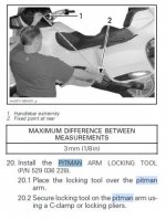
Here are three bits of the factory prescribed procedure from the 2013 RT service manual. The first two deal with locking the handlebar.1) Toe in compare to weight of rider(s) and possibility of towing a camper. Should there be a difference in toe-in for a single rider weight (say 150 lb. vs a heavy rider around the weight of 250 lb.)? Also if normally a single rider compared to normally 2 up. If normally pulling a trailer should this matter for amount of toe-in?
2) I have seen the comments of "locking the handlebars in place ", "locking down the handlebars", "the bars are straight", "locking down the bars". As far as I know there is no locking mechanism on the Spyders to lock the handlebars in a center position. The only method that I have seen used is to stand in the back of the bike and look at the handlebars to see if they look like they are equally left and right. This does not seem to be a accurate method.


At a guess, your friend uses these?
As far as I know there is no locking mechanism on the Spyders to lock the handlebars in a center position.
I have a 2010 RT with 17,000 M.
I am prepared to be corrected, so don't hold back.
As I understand it, the Spyder front end alignment is for "toe in" only. There is no adjustment for caster or camber. Correct ?
If this is correct, I do not understand the big deal about a laser front end alignment.
Does this just use a laser measuring device in lieu of a ruler ?
If this is the case, I would really question the necessity of a laser.
If "toe in" specs are available it would seem to me that it could be done with a ruler.
I am not a Luddite, but I don't like being snookered either.
I have heard the advertisements for high tech laser back surgery. I understand that the only difference is that the incision is made with a laser instead of a scalpel.
It sounds impressive though.
