• There were many reasons for the change of the site software, the biggest was security. The age of the old software also meant no server updates for certain programs. There are many benefits to the new software, one of the biggest is the mobile functionality. Ill fix up some stuff in the coming days, we'll also try to get some of the old addons back or the data imported back into the site like the garage. To create a thread or to reply with a post is basically the same as it was in the prior software. The default style of the site is light colored, but i temporarily added a darker colored style, to change you can find a link at the bottom of the site.

Laser Schmaser ?

Why do you need the track width at the wheels? The concept of the ROLO is to mount the laser on the center of the wheel, then project the laser to the front and to the back. The toe-in is measured by the difference between the left and right laser points an equal distance in front of and behind the wheel centerline. Since the lasers are horizontal for both measurements camber does not affect them.

Yes and no. Your words about projecting forward and aft are correct. The track width measurement is needed to establish the distance between targets at the 0.0 point. Without that, there is no reference of what zero toe will be, and no ability to establish / set the correct toe.
 
If the lasers are parallel to the ground, a target placed in front of and square to the vehicle alignment centre, can be marked at the laser dots. If the target is then moved by the required toe distance (wheel rim diameter for me) then the difference between the dot spacing on the target equals the toe distance.
 
If the lasers are parallel to the ground, a target placed in front of and square to the vehicle alignment centre, can be marked at the laser dots. If the target is then moved by the required toe distance (wheel rim diameter for me) then the difference between the dot spacing on the target equals the toe distance.
Exactly correct!
 
Without that, there is no reference of what zero toe will be, and no ability to establish / set the correct toe.
You will have zero toe when the distance between the laser beams on the front targets equals the distance between them on the rear targets. But rather than adjusting the tie rods you do it arithmetically. If the beams are 1/2" closer in front than back then zero point would be a 1/4" wider in front and 1/4" narrower in back.
 
You will have zero toe when the distance between the laser beams on the front targets equals the distance between them on the rear targets. But rather than adjusting the tie rods you do it arithmetically. If the beams are 1/2" closer in front than back then zero point would be a 1/4" wider in front and 1/4" narrower in back.

Humor me, in Lamonts video, he discusses the first step using the lasers, after tire pressures and if needed belt alignment.

At around 4:40 into the video he begins by measuring track width plus tooling. Followed by, setting targets and rotating lasers horizontal.

https://m.youtube.com/watch?v=2fs8bI3b_BA

This IMotorsports video, also shows them measure track width plus tooling.

https://m.youtube.com/watch?v=WoOyAvShZ9I

This video by Shawn Smoak ido not see him measure track width. Possibly his video format omitted it, but if an alignment can be done without learning what true zero is, I would enjoy hearing how that is possible.

https://m.youtube.com/watch?v=cQ89O379Ljw
 
Humor me, in Lamonts video, he discusses the first step using the lasers, after tire pressures and if needed belt alignment.

This video by Shawn Smoak ido not see him measure track width. Possibly his video format omitted it, but if an alignment can be done without learning what true zero is, I would enjoy hearing how that is possible.

In most of Shawn's videos from work you do not see a step by step process. May be a requirement of his employer.
 
In most of Shawn's videos from work you do not see a step by step process. May be a requirement of his employer.

Very possible and my linking his video is no disrespect to him or the shop he works at. As best I can tell, and he is a continent away, Shawn is one of the true GoTo Spyder techs.

As I mentioned too, very possible his editing the video omitted that portion.
 
You will have zero toe when the distance between the laser beams on the front targets equals the distance between them on the rear targets. But rather than adjusting the tie rods you do it arithmetically. If the beams are 1/2" closer in front than back then zero point would be a 1/4" wider in front and 1/4" narrower in back.


Fair enough, but what reference are you using to establish where to place the targets?
 
I am also going to check mine the next time I do a laser alignment. I assumed, but shouldnt have, that the camber was zero. If it is not zero, then not only will homemade laser alignment tools be inaccurate, but ROLO will be also. Ideally, you would need a device that attaches to the hub with a level on it to ensure accurate track width measurement when the laser is pointed down.

The laser pointers do have levels on them.
 
OK guys, I watched the videos. They do answer one question I've had about laser alignment and that is how the rear wheel comes into play. I see now. The rear wheel is the best reference point available to use to establish where the laser beams need to be in order to be parallel to the frame of the Spyder. The front wheel track, i.e. the distance between the laser beams at the wheels, is used to determine how far from each side of the rear wheel the eventual target points need to be left and right. So we start by by securing the handlebar to keep the steering in a fixed position. Then move the Spyder back and forth a bit to relieve any binding in the steering as Lamont mentions in his video.

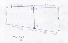
Looking at my sketch below locate the four targets at distance D1 from the front wheel centers. Then move them left and right until the laser points are on the zero target lines. Measure the distance between the target zero lines. Add F & R and divide by 2. That gives you T, the distance between the laser lines at the axis of the front wheels. From here follow the the procedure shown in the videos.

Laser sketch 001.jpg

As far as camber affecting the accuracy of the track distance by using laser points straight down, that is correct, strictly speaking. I suspect real practice has shown that that error is inconsequential in the overall scheme of the alignment process. In fact it's probably less than the errors caused by using ordinary tape measures handled by human hands! I'm sure ROLO wouldn't use lasers pointing straight down if it caused a significant error.
 
Let me share why I'm willing to quibble with the accepted procedure for measuring track width.

I worked for Uncle Sam for over 22 years in monitoring contractors work processes and practices. During that time I came up with the slogan QAQAQA, "The Questioning Approach of Quality Assurance leads to the Quintessential Answer". What I learned is that oftentimes experts and professionals get locked into a certain way of performing a job and did not willingly look for alternative methods. I would often question why they did something in a particular fashion. The end result was one of three results. 1) I learned more about a particular process, or 2) the person who was doing the work would look at or for a different way and end up with an improved outcome, or 3) in defending the process the correctness of the process was verified.

So what I'm saying with respect to measuring the tracking width is not that the usual method is wrong, but there is an alternative way. Better? Maybe, maybe not. My suggested method eliminates the potential error caused by camber and the need to move the bike out of the way to take the measurement. It possibly introduces some error from additional measurements and moving the targets.
 
"This video by Shawn Smoak ido not see him measure track width. Possibly his video format omitted it, but if an alignment can be done without learning what true zero is, I would enjoy hearing how that is possible"


my understanding of true zero is handlebar position when bike is underway.....this explains why he dosent need track width(he knew the bars were straight)
if the bars point to the right,say,then you can adjust them back to centre by adjusting both wheels into the direction of the bars,until bars are straight when underway,then shoot front and back to set the toe,adjusting both track rods the same amount

this takes away the need for bringing the rear wheel into the equation(or making grids or finding the track width)...its only needed to set handlebar position(and greatly simplifies the alignment process).....but only if you can ride the bike,or ask the owner if bars are straight

of course,if the bars are already straight,when the bike is underway, then you only need to shoot front and back to get the correct toe....no need to lock down the handlebars,as you will adjust both tie rods an equal amount

there is only one adjustment for alignment purposes(tie rods)so how many things do we expect to influence?
ANSWER.....2 toe in/out and handlebar position when underway

russ
 
OK, I’m ‘the aussie guy’ and the reason why I specify aiming the lasers on the ‘pie-plates’ (standoffs) to the rear while measuring the width at the front wheels is that the Spyder has a small amount of negative camber. It’s only 3mm (about 1/8”) on average, and that average is important – in other words, it’s slightly different on every bike, which doesn’t say a lot for assembly accuracy. I use a set-square on the FLAT floor so the laser dot hits the edge of the square-blade to give a ‘true vertical’ measurement, and that is marked on masking tape on the floor. Pointing the laser down to the floor will result in a slightly wider width measurement. You don’t need to roll the bike forward or backward to measure the width – you can slide a tape under the curve of the wheels at the exact point below the rear of the wheel rim, so avoiding any parallax error in measurement. That gives you a fairly accurate width measurement.

Yes, the rear of the ‘box’ is measured outward from the rear-most point of the rear wheel rim, so that DOES assume that the rear wheel is running true. But remember that the ‘box’ is about five time the diameter of the front wheels long, so all the measurements at the back of the bike are multiplied five times – that 1/8” camber ‘spread’ can be clearly measured over that distance. That’s the whole point of using lasers. You read the measurements where they are magnified, not at the front wheels.
Lastly, because the Spyder is rear-wheel-drive, the front wheels tend to spread IN MOTION so that any toe-out is exaggerated, any toe-in is reduced. The amount will depend on the amount of wear and tear in front suspension and steering, but is usually in the order of 0.5mm, so the amount of toe-in (at the wheels) needs to be at least that much! Just watching the laser dots on the targets when someone climbs onto the bike doesn’t show any left-right variation – just up-down variation as the bike squats down.

After dozens of Spyders aligned and NOBODY offering anything except praise, I think that this ‘imperfect’ system is quite good enough.
 
..........
After dozens of Spyders aligned and NOBODY offering anything except praise, I think that this ‘imperfect’ system is quite good enough.

:agree: You can spend hours getting lost in the minutiae of an increasingly technical search for absolute alignment accuracy & end up chasing your own tail down the hole, but when push comes to shove, the blunt truth of the matter is that this 'imperfect' system is somewhat more than being 'just adequate' for the Spyder's front end & steering! :2thumbs: And anyone who's enjoyed the results will probably agree that in a significant majority of cases, this 'imperfect' system results in WAAAAYYYYY better rideability & handling/behaviour than whatever method gets used by the factory &/or many dealers! :shocked:

:ohyea:
 
OK, I’m ‘the aussie guy’ and the reason why I specify aiming the lasers on the ‘pie-plates’ (standoffs) to the rear while measuring the width at the front wheels is that the Spyder has a small amount of negative camber. It’s only 3mm (about 1/8”) on average, and that average is important – in other words, it’s slightly different on every bike, which doesn’t say a lot for assembly accuracy. I use a set-square on the FLAT floor so the laser dot hits the edge of the square-blade to give a ‘true vertical’ measurement, and that is marked on masking tape on the floor. Pointing the laser down to the floor will result in a slightly wider width measurement. You don’t need to roll the bike forward or backward to measure the width – you can slide a tape under the curve of the wheels at the exact point below the rear of the wheel rim, so avoiding any parallax error in measurement. That gives you a fairly accurate width measurement.

Yes, the rear of the ‘box’ is measured outward from the rear-most point of the rear wheel rim, so that DOES assume that the rear wheel is running true. But remember that the ‘box’ is about five time the diameter of the front wheels long, so all the measurements at the back of the bike are multiplied five times – that 1/8” camber ‘spread’ can be clearly measured over that distance. That’s the whole point of using lasers. You read the measurements where they are magnified, not at the front wheels.
Lastly, because the Spyder is rear-wheel-drive, the front wheels tend to spread IN MOTION so that any toe-out is exaggerated, any toe-in is reduced. The amount will depend on the amount of wear and tear in front suspension and steering, but is usually in the order of 0.5mm, so the amount of toe-in (at the wheels) needs to be at least that much! Just watching the laser dots on the targets when someone climbs onto the bike doesn’t show any left-right variation – just up-down variation as the bike squats down.

After dozens of Spyders aligned and NOBODY offering anything except praise, I think that this ‘imperfect’ system is quite good enough.

Thank you for posting to this topic.
Right away, I am the person that questioned your method off negating camber effect, by your method of using the square and projecting to the floor.

To keep my questions simple, your projected points to the square and to the floor, they are the basis or datum for rear targets.

If a Spyder has incorrect incoming toe, or worse incorrect and different side to side, doesn’t the dots on the floor become in error, and thereafter, places the targets at the back incorrectly being based off the incorrect incoming toe?

If incorrect incoming toe has no effect on these reference points and the rear target placement, can you explain why?

I understand that a camber setting other than 0.0* will have an effect.

Considering the same scenario as earlier, incoming toe is incorrect, possibly incorrect and differing from each side, in my thinking the likelihood of gross camber error in degrees seems small compared to toe errors, if measured in degrees, and because of this measuring with laser pointed downward seems more accurate. Am I incorrect and if so, can you explain why?

Thanks
 
:agree: You can spend hours getting lost in the minutiae of an increasingly technical search for absolute alignment accuracy & end up chasing your own tail down the hole, but when push comes to shove, the blunt truth of the matter is that this 'imperfect' system is somewhat more than being 'just adequate' for the Spyder's front end & steering! :2thumbs: And anyone who's enjoyed the results will probably agree that in a significant majority of cases, this 'imperfect' system results in WAAAAYYYYY better rideability & handling/behaviour than whatever method gets used by the factory &/or many dealers! :shocked:

:ohyea:


Without any doubt, improving upon an oem alignment using almost any method makes a huge gain in handling.

Currently our Spyder has been aligned via using toe sticks. And oddly, the toe sticks have helped resolve incorrectly done laser alignments on other Spyders.

I truly hope Lindsay is not offended by my curiosity, if anything he has done a nice service for Australian Spyder owners.
 
I will add another wrinkle in this. The Rolo system has changed a bit over the years with regard to camber. The original system did indeed 'assume' zero camber and it was ignored for track width measurement. It was generally 'close enough' for most spyders. A few were off and were caught at the back check measurement front to rear and adjustment made. Experience has shown that most Spyders with any significant camber have other issues that an alignment cannot fix. Now the change came in with the Slingshot. It does have camber and the units are all over the place. It became necessary to measure camber using ( I use a digital angle sensor to make it quick and easy). Track measurement is adjusted for measured camber angles in the worksheet and the alignment proceeds normally from there. It became obvious that using the same procedure for Spyders negates the errors that were showing up and revised settings to correct. IE with the camber angle measurement, the alignment comes out dead on and cross checked first time through...every time.

When the Rykers came out and tooling for those became available from Rolo, we see the same camber angle variances that the Slingshots have. Perhaps a bit less erratic but not as close to true zero as most new Spyders. The camber angle measurement as part of alignment again corrects for this. The camber is not adjustable on any of these but can be taken into account for the other measurements and calculations for corrections. We now measure camber on every alignment, in the end it saves time due to zero corrections at cross check.

The Rolo system is only as good as the tech doing the alignment. Its only measurement tools with instructions on how to use. Buying the tools does not make alignment experts.
 
It became obvious that using the same procedure for Spyders negates the errors that were showing up and revised settings to correct. IE with the camber angle measurement, the alignment comes out dead on and cross checked first time through...every time.

We now measure camber on every alignment, in the end it saves time due to zero corrections at cross check.
That certainly dispels the thought that error caused by ignoring camber is not significant!
 
I use a set-square on the FLAT floor so the laser dot hits the edge of the square-blade to give a ‘true vertical’ measurement, and that is marked on masking tape on the floor.

After dozens of Spyders aligned and NOBODY offering anything except praise, I think that this ‘imperfect’ system is quite good enough.
But your method can be influenced by existing toe-in, right? Yes, you do get a point that is not affected by camber, but you're trading that for an effect caused by toe-in since the square is a few inches in front of the wheel axis.

The ideal laser would be one that can be adjusted to be level and plumb in all three axes, keep the x y z origin point of the beam rotation stationary, and keep the horizontal beam perpendicular to the wheel axis.

Why do you choose to not also project the laser to a pair of targets an equal distance in front of the wheels like the ROLO? Doing so would give you twice the measurement you get with the rear projection only.

The key phrase in your comment is "good enough"!
 
Back
Top