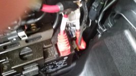
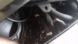
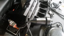
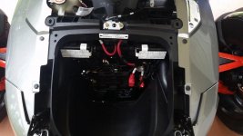
• There were many reasons for the change of the site software, the biggest was security. The age of the old software also meant no server updates for certain programs. There are many benefits to the new software, one of the biggest is the mobile functionality. Ill fix up some stuff in the coming days, we'll also try to get some of the old addons back or the data imported back into the site like the garage. To create a thread or to reply with a post is basically the same as it was in the prior software. The default style of the site is light colored, but i temporarily added a darker colored style, to change you can find a link at the bottom of the site.

F3 Customer Accessory Circuits

Gordon

New member
The front circuit is located behind the storage box. Just reach into the hole and pull it out (not wire tied). In the pic it is laying across the red insulator. The middle circuit is under the left service panel. You only need to cut the wire tie at the top of the two pictured (wire ties were black…used white after cutting both). Both of these are just the harness (no plug). The rear circuit Is under the passenger seat. Plug is provided. Wiring is a black wire (ground/negative) and purple with a yellow stripe (positive). Power is only applied with the engine running. Fuse is located in the right fuse box (behind the storage box) position F6 10Amp.

attachment.php
attachment.php
attachment.php
attachment.php
 

Attachments

  • Front.jpg
    Front.jpg
    51.1 KB · Views: 1,360
  • Middle.jpg
    Middle.jpg
    27.1 KB · Views: 1,310
  • Rear2.jpg
    Rear2.jpg
    47.2 KB · Views: 1,249
  • Right fuse box position F6 10A.jpg
    Right fuse box position F6 10A.jpg
    41.8 KB · Views: 1,242
I should of said that I did not open the wiring harness of the front and middle to verify, but I am assuming that there are already wiring connectors and there is not a rubber boot like found on the rear.
 
Adding Keywords to help with search

Keywords: add install gps heated grips gloves cellphone cell phone power plug outlet


These are just what I could think of quickly. Please add to them.
 
Last edited:
Front and middle have no connectors just wires
Fwiw suggest using small scissors to get the sticky fabric tape off to get to the wires
a hobby knife is too sharp.
 
One more question

Does the middle power source come from the bottom or the top. If it is coming from the bottom and no plug is connected, one might expect it would be possible to just pull the wires out at the top and not have to cut any zip ties. Am i correct on this, or is it possible the newer Spyders have a connector on the end of the accessory power?
 
Does the middle power source come from the bottom or the top. If it is coming from the bottom and no plug is connected, one might expect it would be possible to just pull the wires out at the top and not have to cut any zip ties. Am i correct on this, or is it possible the newer Spyders have a connector on the end of the accessory power?


There is no connector on the end, just insulated wires. You will have to undo the fabric wire wrap but the wires were long enough to add connectors and plug in to the back of my dash power outlet.

Be advised that these are only powered when the engine is actually running.
 
Friction Tape

There is no connector on the end, just insulated wires. You will have to undo the fabric wire wrap but the wires were long enough to add connectors and plug in to the back of my dash power outlet.

Be advised that these are only powered when the engine is actually running.

My Customer Accessory lead was actually wrapped in Friction Tape, something I haven't seen used in decades.
 
I was looking for accessory plug under left service panel. Ended up cutting this wire I think. What is this?

3718aab1fda77d890b4b5b4a84dd9147.jpg


Sent on Note 5 in Taptalk
 
Thanks for the pics of this.
The front circuit is located behind the storage box. Just reach into the hole and pull it out (not wire tied). In the pic it is laying across the red insulator. The middle circuit is under the left service panel. You only need to cut the wire tie at the top of the two pictured (wire ties were black…used white after cutting both). Both of these are just the harness (no plug). The rear circuit Is under the passenger seat. Plug is provided. Wiring is a black wire (ground/negative) and purple with a yellow stripe (positive). Power is only applied with the engine running. Fuse is located in the right fuse box (behind the storage box) position F6 10Amp.

attachment.php
attachment.php
attachment.php
attachment.php
 
I did the same thing, do i need to solder them back together, not sure if I cut or if they were already not connected to anything.
 
For a GPS I suggest using the existing GPS connector under the left rear side panel. It comes on with the key and goes off with the key after a 10 second delay. That's where I have my Garmin plugged in. If you have a gps with audio out, the connector for that (1/8" headphone male) can be found where shown. If you don't have audio out, you can modify a Garmin to have one. Instructions at his link. >CLICK ME<

Connectors used for the +12 GPS circuit. >CLICK ME<

gps2.jpg
 
Last edited:
Back
Top