• There were many reasons for the change of the site software, the biggest was security. The age of the old software also meant no server updates for certain programs. There are many benefits to the new software, one of the biggest is the mobile functionality. Ill fix up some stuff in the coming days, we'll also try to get some of the old addons back or the data imported back into the site like the garage. To create a thread or to reply with a post is basically the same as it was in the prior software. The default style of the site is light colored, but i temporarily added a darker colored style, to change you can find a link at the bottom of the site.

'24 F3 Customer Accessory Circuits don't match manual - splice into them or... ??

jjpgator

New member
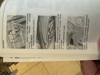
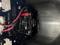
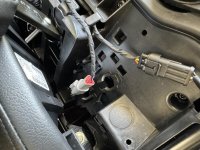
Just bought a 2024 F3S and I'm mµlooking to add some lights. The manual states that there are 3 Customer accessory circuits available. One under the frunk; one, the left service panel; and one under the passenger seat. I’ve checked all three and they don’t look anything like what is in the manual, or what I had in previous Spyders. Do I need to splice directly into the wires to access these?

IMG_1918.jpg - IMG_1920.jpg - IMG_1921.jpg
 
Last edited by a moderator:
I have found the manuals to be generic in nature and missing most of the useful info.
 
Last edited by a moderator:
A lot of folks here (me included) just added a small FUSE box connected to the battery and used that as needed. I think I paid $8.00 for 6 circuits... Dee what "Banggood" has to offer... Mike (y)
 
ON my 2022 RTL there was no accessory wire on the right side, so I spliced into a wire labeled power using posi-taps. Installed my GPS and it powers up when my RTL is turned on.
 
On my 22 F3S I have found and used all but the rear cust acc wiring.
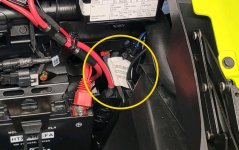
If it's the same as mine, the wires will be taped together and then sealed. It's all black. The frunk wires to the right of the battery looking at the Spyder from the front. I had to dig mine out. They were hiding in plain sight.
The left side panel is where the 2nd customer accessory wiring is. It should also have a white tag indicating the cust acc wiring.

The rear looking from the back of the Spyder it's under the seat or cowl on the left side looking fwd. Mine was two pinkish colored female spade butt connectors.
 
Just purchased a 2024 F3 Limited Special and want to hookup a Garmin XT. Owners manual says there is an accessory circuit under the left service panel but I cannot find it. Went to the dealer and he could not see it either on a showroom model. Has anyone with a 2024 F3 Limited found the accessory circuit under the left service Panel?
 
You may need to look a bit deeper. On my 2023 F3-S, the frunk accessory circuit was almost "outside" the frunk area, in fact I think I see the white paper label in your image. Mine was wire-tied to a harness and somewhat of a PIA to free up and pull into the frunk. It also was not very long. I used a red wire tie to keep it in the funk area. (See the image below)

The left side lines were the same way - folded up and deep inside the cavity wire-tied to a harness. Look for a paper tag as your first clue.

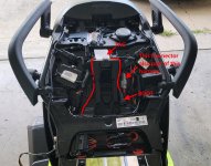
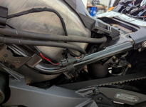
The tail circuit was plainly in sight with a black rubber boot. In your last image, it is clearly not in the location where it's supposed to be. I can see the locating tabs that hold the wires in your picture and there is no wire there. BTW, the rear circuit actually comes into the tail from the opposite side and wraps around to where your picture shows. (See my attached image.) Maybe starting at that point and looking around to see if someone just didn't route it properly at the factory?

Or...

Perhaps Can-Am changed these and didn't update their manuals? :dontknow:


I don't intent to ruffle any feathers, but I would advise against adding a fuse block and running directly from the battery. Parasitic draw is real and if done wrong, can damage the battery or worse - the electrical system. The one time you accidentally leave something on and come back to a dead battery... Using the customer accessory circuit gives you 10 amps worth of power (8A actual - always leave 20% for a safety margin) is the safest and cleanest option IMO. The circuit is switched; it only outputs 12vdc when the motor is running; and the battery is charging.

The attached image shows my tail, and I highlighted the path the wire takes. Keep in mind, my tail has been cleaned up a little, meaning there was a lot of extra wire for the customer accessory circuit, so I wrapped it up and placed it all under the tag. Good Luck!

:cheers:

ACCESS CIRCUIT_REAR.jpg - Front Access oy circuit.jpg
 
Last edited:
Any update on this from the OP? Curious minds would like to know what you found out! And the rest are peeved that you likely got a resolution, but didn't take the time to share it after asking for help. :lecturef_smilie:
 
Any update on this from the OP? Curious minds would like to know what you found out! And the rest are peeved that you likely got a resolution, but didn't take the time to share it after asking for help. :lecturef_smilie:

It appears that the OP came, posted the opening post here, then left the Forum about an hour later and has not been back since... That could be for a variety of reasons, pressing health issues; accidents; dealing with floods &/or tornadoes - who knows?? Maybe they just haven't had the time &/or opportunity to check back yet :dontknow: Not everyone visits the Forum every day, altho unless they're actually out riding, why they wouldn't check in is beyond me! :p

Still, it happens, sometimes a lot, and there's no use in getting peeved over that - it'll just raise your blood pressure, probably increase the damage you inflict on your keyboard, likely end up increasing your risk of heart attack &/or a stroke too; and there's nothing you can do about it anyway, so... :rolleyes:

Besides, posting about it & having a bit of a dig probably won't help anything much either - in fact, it might even convince some not to even bother coming here &/or asking their questions in the first place - so all round, it's very likely better for you; it's almost certainly better for all the other members; and it's better for the Forum as a whole if posting about it like that is best avoided, and you just take it on the chin as part of the rich tapestry of life; and instead, try to Ride More, Worry Less! ;)

Just Sayin! (y)
 
I don't intent to ruffle any feathers, but I would advise against adding a fuse block and running directly from the battery. Parasitic draw is real and if done wrong, can damage the battery or worse - the electrical system. The one time you accidentally leave something on and come back to a dead battery... Using the customer accessory circuit gives you 10 amps worth of power (8A actual - always leave 20% for a safety margin) is the safest and cleanest option IMO. The circuit is switched; it only outputs 12vdc when the motor is running; and the battery is charging.
:cheers:

Or, maybe getting an accessory fuse block that can be switched on and off and use the power from the Spyders accessory circuit to do the switching. Then you can have multiple outlets at 8 amps or more.
 
Because "Curious minds would like to know"... and because I finally found this thread, waiting in suspense as I read each post, only to be let down. Also, I spent my weekend disassembling the entire body looking for wires so I thought someone else might appreciate it.

I have a 2024 F3L.

I can confirm that the accessory power under the left front panel is missing on my 2024. There is an Accessory fuse location, with a fuse, in the fuse box. However, I think it must be for the wire/plug behind the button blank to the right of the ignition key. There are left and right plugs behind each fog light cavity, which are probably wired to the plug.

The GPS accessory power is still present on the left side of the bike. It's switched on with the key. They put it in the perfect place so you have to remove the upper and lower panels to get to it. This connector fits: Amazon Connectors.

1744052593548.png

Also, the bottom of the lower panels on both sides were 'floating'. There is a hole in the panel and matching hole on the underside of the luggage for a panel insert but they were missing. I'm not sure if these fell out or what. I ordered some panel pins to secure them but I don't have them yet.

1744053243758.png
 
Sorry everyone, but I haven’t logged on in a while. I was never able to find an accessory circuit so I just wired my lights directly to the battery and use a remote to turn them on and off.
 
Back
Top