• There were many reasons for the change of the site software, the biggest was security. The age of the old software also meant no server updates for certain programs. There are many benefits to the new software, one of the biggest is the mobile functionality. Ill fix up some stuff in the coming days, we'll also try to get some of the old addons back or the data imported back into the site like the garage. To create a thread or to reply with a post is basically the same as it was in the prior software. The default style of the site is light colored, but i temporarily added a darker colored style, to change you can find a link at the bottom of the site.

LED Driving Lights

Fearless

New member
G'day everyone

Question for the electrical gurus here.
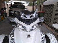
2014 RTs

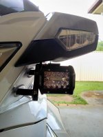
I wish to mount a pair of LED driving lights. Are the lights switched positive or negative.

I have taken a pigtail from the high beam through a switch and to the relay. (pin 86). Power is pin 30, battery negative is pin 85 and lights is pin 87. There is a negative lead from the pigtail so I put that in the negative side of relay.

started bike up, lights as normal. Turned high beam on and tried the driving lights. Promptly blew the 20amp mini fusable link. in the fuse box.

Any ideas as to what I have done wrong.

I have wired quite a few driving light setups before so no stranger to doing this.

Many thanks for input.

Cheers
Frank
 
Where did you get the power for pin 30? Don't get it from the lights fuse, get it straight from the battery (through a fuse, of course).

.
 
Thanks guys

Managed to sort it all out.

Pigtail from high beam was backwards - positive and negative were swapped about. Pin 30 power is from battery (fused 10amp).

Stupid mistake from me for not checking that power comes from the right wire.

I will post photo of how I mounted it later when I can.

Edit

Photos of lights installed. All my measurements are metric.

What I did was purchase some 16mm solid plastic rod.

Cut 2 lengths 30 and 75mm. Use a straight edge to make sure it is vertical and check measurement. These fit into the holes of wind deflector.

Drill 6mm hole through the length (lathe is handy for straight hole).
You will need longer bolts/screws, flat and spring washers. Flat washer between the bracket and the plastic rod.

Bracket: 30mm angle iron
Cut to 160 to 200mm long. At the 100mm bend 90 degree.
The wind deflector holes are 60mm center to center. Measure 20mm from bottom of bracket.
Then measure 60mm for the other hole.
I had to trim one side of the angle to allow for adjustment. Also try to make the horizontal part of the bracket as short as possible to stop any vibration.

The lights I used I got from a online 4wd store. 4” LED light bar. Current is 1.74 amp and 25 watt.

Wiring is as per any driving light setup (see Google). I did purchase a pigtail https://www.ebay.com.au/itm/123831660649. Saves having to cut into stock wiring. Just check that the colour coding is correct (mine was reversed).

Will have to see how much difference they will make to night riding.

In Australia our low beams are the US spec fog lights, highs are up top. I have a kit made by one of our riders here that turns on all 4 lights when high is selected. Also all my globes are LED.
View attachment 179435
 

Attachments

  • IMG_20200306_112303.jpg
    IMG_20200306_112303.jpg
    74.3 KB · Views: 37
  • Lights.jpg
    Lights.jpg
    38.2 KB · Views: 46
  • IMG_20200311_075252.jpg
    IMG_20200311_075252.jpg
    31.9 KB · Views: 26
Last edited:
... the Japanese convention of doing almost all switching on the ground side of the load. US convention is to switch the power side.

My "Japnese" Toyota Sienna was built entirely in the US. There are some items that are "switched hot" and others that are "switched ground".

I don't think the country of origin is the issue, it's more likely the item that is being controlled.

My classic Suzukis use switched hot for everything except the horns, which are switched ground. :dontknow:

.
 
Back
Top