Santa was kind enough to bring me a Motorcycle dual camera kit (crash cam)
Mounting has been easy, as has running cables, but I was wondering about the electrical.
My spyder is an RTL 2017 model, and I had the dealership wire in two Baja Design S2 Pro lights (to supplement High beam) a while back, so some of the hard yards are done. The aim was tap into the "ignition Signal" used for the driving lights + another relay and ride off into the sunset.
My Pondering - after I add a 2nd relay for the crash cam will I overload the Ignition signal to the two relays,
Example : does it only provide say 1W of power to activate one relay, and adding a second would be a load of 2W causing it to overload it (and possibly causing the CANBUS to begin a campaign of hatred against me)?
I understand the load created by the gadgets are supplied via the battery courtesy of the relays, but don't have enough knowledge about the limits of the "signal" from the Ignition circuit used for the lights.
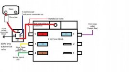
I drew these 3 drawings to try to explain that which I don't have the terminology for.
Existing - what has been installed by the dealership for the lights.
Intended Install - is just tapping into the "signal" from the ignition to source that "signal" for the 2nd relay
Or Should I - add a relay that maintains the existing draw on the ignition circuit, and allows a 3rd relays to be added for the crash cam.


So,
Mounting has been easy, as has running cables, but I was wondering about the electrical.
My spyder is an RTL 2017 model, and I had the dealership wire in two Baja Design S2 Pro lights (to supplement High beam) a while back, so some of the hard yards are done. The aim was tap into the "ignition Signal" used for the driving lights + another relay and ride off into the sunset.
My Pondering - after I add a 2nd relay for the crash cam will I overload the Ignition signal to the two relays,
Example : does it only provide say 1W of power to activate one relay, and adding a second would be a load of 2W causing it to overload it (and possibly causing the CANBUS to begin a campaign of hatred against me)?
I understand the load created by the gadgets are supplied via the battery courtesy of the relays, but don't have enough knowledge about the limits of the "signal" from the Ignition circuit used for the lights.
I drew these 3 drawings to try to explain that which I don't have the terminology for.
Existing - what has been installed by the dealership for the lights.
Intended Install - is just tapping into the "signal" from the ignition to source that "signal" for the 2nd relay
Or Should I - add a relay that maintains the existing draw on the ignition circuit, and allows a 3rd relays to be added for the crash cam.
So,
- Is the dwg titled "Intended install" OK?
- Or is dwg titled "Or Should I" the required method?
- Or am I over thinking it?
")