• There were many reasons for the change of the site software, the biggest was security. The age of the old software also meant no server updates for certain programs. There are many benefits to the new software, one of the biggest is the mobile functionality. Ill fix up some stuff in the coming days, we'll also try to get some of the old addons back or the data imported back into the site like the garage. To create a thread or to reply with a post is basically the same as it was in the prior software. The default style of the site is light colored, but i temporarily added a darker colored style, to change you can find a link at the bottom of the site.

Where to install aux fuse block for 2015 RT-S

fratzba

New member
Well. it's project time, and one of the first on my list is to install an aux fuse block.

Where is the best place to mount it? I'd like it to be somewhere that won't be in the way for servicing, especially when the frunk needs to be removed. but not tooo difficult to get to in case a fuse needs replaced.

I've got a bunch of stuff that needs extra power (GPS, horn, heated gear, etc...)

Any suggestions? This is for a 2015 RT-S.

Thanks! -Fratz
 
AUX Power Locations

Well. it's project time, and one of the first on my list is to install an aux fuse block.

Where is the best place to mount it? I'd like it to be somewhere that won't be in the way for servicing, especially when the frunk needs to be removed. but not tooo difficult to get to in case a fuse needs replaced.

I've got a bunch of stuff that needs extra power (GPS, horn, heated gear, etc...)

Any suggestions? This is for a 2015 RT-S.

Thanks! -Fratz
I have a different model F3's, I have lots of experience with various model motorcycle's--but locating the aux power leads as been a major new inconvenient experience for me. they double tape wrap most of them---I'm guessing Spyder's are jet ski's or snow mobiles with wheels. extra tape shielding to protect from the weather elements.--None visible without removing layers of electrical tape plus they are tie-rapped to upper housing--There are several manuals available on-line but none are easy to read. BRP does an excellent jobs with photos's showing the easiest access locations--not so much with the difficult locations. Good luck. Also I have never heard of so many complaints & time delays from any other bike mnfg. If it was a Honda, Yamaha, Suzuki, etc--you'd forget the dealers location from lack of need for assistance...
 
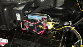
On my Spyder RT 2010 SE5 model I fitted the extra fuse block under the left hand side service cover located under the front trunk hood see

http://www.spyderlovers.com/forums/...u-identify-these-brackets&p=366988#post366988

The fuseblock was an FZ1 fuseblock

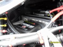
I have used the same location for a fuseblock on my Spyder RT SE6 2015 model but used a PDM60 fuseblock

Thanks for the suggestion and link!

I had looked at this location as well, but am concerned that you would have to remove it in order to take the frunk off. Have you had any issues with this?

Thanks! -Fratz
 
Where did you find space in there with the battery jumper posts in there?


If you remove the service cover located under the funk lid, under the LHS (as sitting on the Spyder) you will see a bar with some studs underneath the Headlamp – I made a shelf for my PDM60 Fuse box to sit on
It was bolted on to the shelf and the shelf was then bolted using the studs to hold
it in place


The PDM60 is very smal and there is plently of room for it


I accessed the + and - terminals from the battery from the back so the leads can
just be disconnected should the funk need to be removed
The leads are zip tied to the frame above the a frame suspension A Arms and have been protected in hard plastic tubing to give protection
The switched live was taken from a connection located near that bar with the
studs as there appeard to be a blank off connector behind the funk and I checked
one of the wires and it was only live with the key on


The location of the PDM60 Fuse box allows easy accces to the console for the extra
equipment you need to get power to


You just have to programme the PDM60 before you fit it – The PDM60 comes with
full instructions


See http://pdm60.com/


Just allow some extra length of leads should you need to remove the PDM60


The advantage is you don't need to remove it to replace fuses or a relay
The location means you can see the LED's showing the state of the circuits when
the PDM60 is on


I fitted mine in June 2015 and have not needed to touch it


I have added some waterproof materinal over the top of it below the service cover
just to keep any water away from it but it is sealed


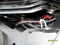
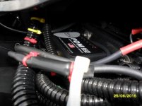
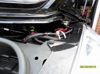
Here is a couple of Photos to show the PDM60 in Place


attachment.php
attachment.php
attachment.php
attachment.php


Attachments

  • SAM_0890 (800x600).jpg
    SAM_0890 (800x600).jpg
    47.5 KB · Views: 651
  • SAM_0891 (800x600).jpg
    SAM_0891 (800x600).jpg
    63.1 KB · Views: 646
  • SAM_0892 (800x600).jpg
    SAM_0892 (800x600).jpg
    48.3 KB · Views: 640
  • SAM_0893 (800x600).jpg
    SAM_0893 (800x600).jpg
    57.7 KB · Views: 640
Install PDM60

Hello brothers and sisters. I see photos of installation but not clear of the location of wiring to perform on my Spyder RS. Would I have to remove the hood to place the negative cable as I wish to add a negative busbar for negative leads.
 
Hello brothers and sisters. I see photos of installation but not clear of the location of wiring to perform on my Spyder RS. Would I have to remove the hood to place the negative cable as I wish to add a negative busbar for negative leads.
You'll be better off to ask this question in the RS subforum. This thread is in the RT Touring subforum so the members who need to see this question may not. I'm sure there is a big difference between the RS and RT as to installing the fuse block.
 
Install PDM60 to Spyder RS

You'll be better off to ask this question in the RS subforum. This thread is in the RT Touring subforum so the members who need to see this question may not. I'm sure there is a big difference between the RS and RT as to installing the fuse block.
Thank you I will check out the RS info.
 
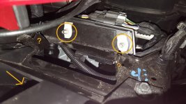
Referencing the attached picture...

Eddie: Are the 2 circled bolts where you attached a shelf? Did you just take a piece of sheet metal, bend it, drill out some holes then attach onto the bolts coming through with some nuts? Also I notice in some of your pics you had wires routing down where the arrow is. Doesn't that area come off with the frunk? Seems you would have to disconnect those to remove frunk?

Fratz: What did you ever wind up doing?

Has anyone ever identified what if anything is made to go on the brackets with the ?

20170430_105257.jpg
 
Referencing the attached picture...

Eddie: Are the 2 circled bolts where you attached a shelf? Did you just take a piece of sheet metal, bend it, drill out some holes then attach onto the bolts coming through with some nuts? Also I notice in some of your pics you had wires routing down where the arrow is. Doesn't that area come off with the frunk? Seems you would have to disconnect those to remove frunk?

Fratz: What did you ever wind up doing?

Has anyone ever identified what if anything is made to go on the brackets with the ?

View attachment 147004

Is that a picture of your 2015 RT below the left headlight?
 
Referencing the attached picture...

Eddie: Are the 2 circled bolts where you attached a shelf? Did you just take a piece of sheet metal, bend it, drill out some holes then attach onto the bolts coming through with some nuts? Also I notice in some of your pics you had wires routing down where the arrow is. Doesn't that area come off with the frunk? Seems you would have to disconnect those to remove frunk?

Fratz: What did you ever wind up doing?

Has anyone ever identified what if anything is made to go on the brackets with the ?

View attachment 147004

Sorry for the delay I am away
I ran a + & - lead up from the battery terminals using ring connectors
so you just need to take the leads off if removing the frunk
The only other connector is to tap into a power which is live when ignition is on

I did use the bracket, bent a plate for the PDM60 to sit on and used 2 bolts & nuts to secure it to that bracket
 
Fatz, check out: tricledusa.com to see their fuse box. Sure looks like it will do what you want.

(This is an old thread Jake...)

I already had the fuse block picked out, I'm using a pdm60. It's programable, and does exactly what I need.
This thread was just about where to install it, which I did in the left service compartment in the frunk about a year and a half ago :-)

-Fratz
 
Is that a picture of your 2015 RT below the left headlight?

Yes, right under the black trim panel.
I take it you are looking to install a fuse box in that area, or have you already? I just put my fuse box in there loose. That way I can pull it out to plug and unplug both wires and fuses as I need. Makes it a lot easier than trying to manipulate things inside a cramped location. At least I think so.
 
Yes, I just installed a Neutrino Black Box in there. I did make a shelf for it and zip tied it so it wouldn't move around much. I'll probably document it and the many other things I did at some point in the diy/mods section but here's a quick pic.
20170506_220230.jpg
 
Last edited:
Mine is under the trailing lip of the trunk lid on the left side. Easy access to wires etc.
 
Back
Top