I personally would not take the mirrors apart. Several people on this forum have reported breaking the tabs off. Drilling the hole instead is no big deal. At the risk of making a simple job complicated, I'll outline what I did and show some photos:
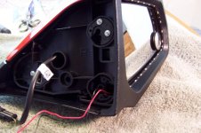
First, remove the lower two-wire spring clip -- two screws.
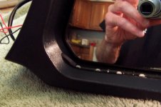
Second, the inside lower corner is where I chose to drill a small hole. To avoid the drill bit wandering, I first just twisted the bit in my fingers to make a small depression in the right spot, then put the bit in the drill and made the hole. Tape the glass so you don't accidentally scratch it.
You can fish the wires thru the drilled hole and thru the open hole where the spring clip should be.
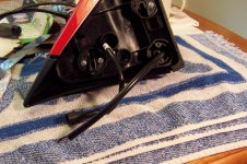
I put sheathing over the new wires but given they're all inside the plastic mirror housing I don't know if that's necessary. I'm a belt and suspenders kind of guy.
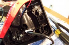
Use a stiff wire like a single-strand copper wire to fish the new wires back thru the lower hole and thru the mirror and out thru the central hole.
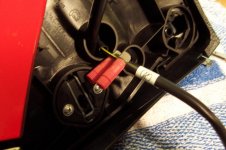
Use posi-taps to tap into the original turn-signal wires. LED's are polarity sensitive so you need to make sure you get + to +, etc. You can test at this point with a 9-V radio battery and confirm that all is working. Then shove the posi-taps back inside the mirror housing and your'e done.
Remember when you're choosing where to tap into the original wires that you should connect at a location near the mirror housing. After putting the connectors inside the mirror housing you want a long original lead still remaining so you can connect easily back to the bike and when you or an unknowing mechanic pulls the mirrors off the next time, they won't be straining the posi-tap connections.