• There were many reasons for the change of the site software, the biggest was security. The age of the old software also meant no server updates for certain programs. There are many benefits to the new software, one of the biggest is the mobile functionality. Ill fix up some stuff in the coming days, we'll also try to get some of the old addons back or the data imported back into the site like the garage. To create a thread or to reply with a post is basically the same as it was in the prior software. The default style of the site is light colored, but i temporarily added a darker colored style, to change you can find a link at the bottom of the site.

Runining live/netural feeds fronm the battery on an RT SE6 2015 Model

eddieshep999

Active member
I am about to get a new RT SE6 2015 Model

I want to add an extra fuse box and a seperate live feed to a relay to power up a Horn (Stebel Horn)

Is it easy to get access to the Front Battery to attatch the Fuse Box Cables and a New Live Feed into the main body of the Spydier without having to drill holes in the front trunk

I know the battery in the Front trunk has a cover over it so the leads would need to go from the back of the battery into the main body

Anyone done this and if so how have you managed it (I don't want to have the remove the front trunk to achieve the feeds)

Thanks

Eddie Sheppard Reading UK
 
Aux 12VDC power pickup

The nice thing about the new ACE engine is it has a alternator. There is a better way of picking up the needed power without loading up the battery terminals with wires. Routing the wires to the battery without taking the Frunk off is blind at best where the wires are and will they be subject to damage between the trunk and frame over time.

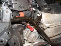
You will find that the left side of the engine has a ton of space because there is no radiator or oil tank just the horn. before doing the following suggestion you must gain access to the battery by removing the panel located in the trunk. The procedure is in the Operators manual. Once you get to the battery remove the big black wire on ground (earth) terminal and insulate it from coming in contact with the battery terminal. Remove the left side pop off panel and any other panels you think is needed to mount you fuse panel and horn. You can easily pick up the need 12vdc source by using the big terminal on the alternator and running the earth wire to the frame. The corner of the gas tank is a good ground source. once you are done all you have to do is reconnect the battery and cover.


attachment.php
attachment.php


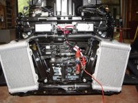
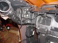
Removing the Trunk is the same as as before. There are 2 side screws, four top bolts and 2 bolts on the bottom that are hidden but located the same. All the trunk connectors are located on top far right and left side under the triangular pull off panel. Disconnect the Trunk release cable, micro-switch connector and electric trunk release connector if equipped. The only thing left is loosening the hose clamp on the left side for the air duct connection.

attachment.php


Send me a PM with your E-mail address and I'll send you the document that has a ton of info on how the dealer put it together.
 

Attachments

  • JT project 005.jpg
    JT project 005.jpg
    86.2 KB · Views: 255
  • heated power 001.jpg
    heated power 001.jpg
    74.5 KB · Views: 251
  • 2014 rt fog lights 022.jpg
    2014 rt fog lights 022.jpg
    77.3 KB · Views: 250
Thanks Doc

I will send you a PM for the info as this may prove very useful

I just have a questions if you don't mind answering it

Ref Using the + Positive terminal on the Alternator

Can this be accessed without removing the trunk Just by removing the panel which use to cover the Oil tank on the 998 Model

Looking at the 2nd picture it looks like it would be easy to get to saving me having to remove the front trunk

attachment.php


When you disconnect the + Positive terminal and add a terminal or 2 when reconnecting the + Positive back on to the Alternator will this once on
and with the new terminals in use, could this upset the Alternator, Computers or the Can Bus system
 
Last edited:
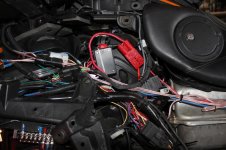
I agree, tapping off at the alternator is a good source, I ran mine to 100 amp fuse, then a quick disconnect (100 amp) then to master distribution panel. I bought a fuse panel from Buss that I could wire up myself and includes space for relays. Since you pin the fuse panel yourself this can be customized as necessary. Naturally I do not use all 100 amps since the bike needs power to run as well but this assures I am well covered at the Power Distribution Panel.

I then took a mutiple feeds off of the distrubution panel and ran them to the fuse panel, then one large feed wire from the MDP to the relays. The relays are triggered from a circuit on the bike that is only hot when the RT is running so I cannot accidently run down the battery. Then from the relays to fuses then to the various accessories I have added.

Part of the fuse panel I built has a hot all the time side which is not switch and comes right of the MDP. This is for those items that need constant power but few assessories require this (an example is my amp whitch is interally switched bye the blue feed and hot all the time).

If I recall correctly I have 15 switched fuses, 5 unswitched and 3 relays in the panel. The fuse panel is mounted on the left side (as you sit on the bike) and accessable by removing the snap off side panel. I also mounted a good ground bar with mutiple screws for all of the device grounds to terminate at. Works great and makes adding accessories very easy.

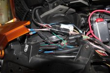
In the pictures below you can see the large fuse holder (Black, the quick disconnect ( in Red) and the distribution panel (has a White snap tie). You can also see the waterproof custom disconnects I make up for ease of disassembly. All modules on the bike can be removed by simply disconnecting one or more connectors. You can also see the ground bar in the lower left.

While on the subject of grounds, it is important to have as little resistance as possible to preven issues. I ran seperate ground right from the battery to ensure the best return path to the ground bar.
 

Attachments

  • Left Side Disconnets.jpg
    Left Side Disconnets.jpg
    67.2 KB · Views: 57
  • Right Side Prior to Disconnect.jpg
    Right Side Prior to Disconnect.jpg
    67.9 KB · Views: 49
Last edited:
Back
Top