It is frustrating quite often when thing go wrong, many times multiple things in a row.
But it makes me happy when I read such kind words

. When I sometimes question this whole project, small things like that allow me to keep going.
So, back to the topic

.
I've made some calls to spring producers and steel suppliers and found one company which sells high quality steel bars and tubes. It is around 2km from my hope, and they've had 16mm 40HM+QT in their warehouse. I've had to buy one whole bar (6m), but it was around 30 USD.
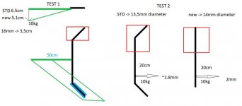
Again, I've made same tests and I think I'm finally happy with the results. I've updated the image in my previous post with tests. Test 1 indicated around 3.5-3.7cm which is almost twice as strong as original. But there is an error for sure (explained also in previous post), and the bigger the difference in results there is, the more significant error is when calculating change 100%. For example, if 1cm of bending is due to error, then actual results are 5.5, 4.1 and 2,5. 2,5 is more than twice as strong as 5.5. Fortunately I was able to observe how everything is bending during tests and I don't thing there is so much additional bending due to material as test tool.
There is another thing I'm changing which is ride height. I don't want to stiffen the front shocks but I am sometimes hitting road with front plate under the trunk when there are big holes. So, I've decided to add 4cm of additional height to the front.
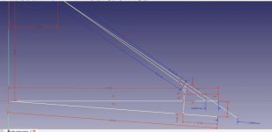
With FreeCad I've started to check where new lower mount for shock should be to add additional height. Having in mind that I don't want to destroy old mounting point, there are two possibilities - add mounting plate with hole lower and closed to frame, or move it up.
Depending on new location differrent forces might appear.

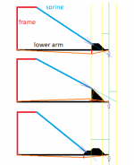
This is my overview for left lower arm. When shock mount is placed further from arm (up direction), then separation of mount from arm might occur. When it's close to the arm, and loser to the frame, there is higher probability that arm will bent because shock will act at start of lever.
Current original placement is almost perfect, because force from shock is directed to where force from wheel is applied.
So, i've decided that I will choose this option which guarantees lowest distance of extension of fforce fro shock to point which acts as force from wheel (end of lower arm) - option number 2. But, I will extend the mount towards the frame to minimize possibility of cracking near the arm.
Some calculations for this option in ca software:

Originally mounting hole is around 4.5cm from center of the arm. Now it should be 9cm.
If, because of shape of current mount, welding and shaping of additional plates will be difficult, it's possible i will just add some simple plates to have additional hole in the mounting. There holes will not hold the shock in that scenarion, instead they will hold separate mounting adapter.
This option would act as extension for the shock which would keep the forces in same place. And making new extension adapter would be fairly simple and would not require too much welding on the arm. I'm very much affraid of tearing and cracking and my welding skills are far from perfect. This is critical place so attention to details is really important here. There must be no doubts about rigidity of this modification.


