• There were many reasons for the change of the site software, the biggest was security. The age of the old software also meant no server updates for certain programs. There are many benefits to the new software, one of the biggest is the mobile functionality. Ill fix up some stuff in the coming days, we'll also try to get some of the old addons back or the data imported back into the site like the garage. To create a thread or to reply with a post is basically the same as it was in the prior software. The default style of the site is light colored, but i temporarily added a darker colored style, to change you can find a link at the bottom of the site.

RT rescued from graveyard

As a suggestion towards simplification, and seeing the amount of effort you are expending. Have you considered, and you seem capable, to remove the Spyders oem chassis computer and engine computer setup entirely, and remove the applicable input transducers? Then find an engine computer from an Aprillia for engine management. Ridden smartly, you might only wish to incorporate an abs control system.

That was my first idea but I wanted to finish the frame and afterwards check if engine is working. When I bought it everything was in pieces therefore I could not start the engine.
Now after solving many problems I did not expect to see I am a little bit exhausted and for the time beeing I will keep it as is. I will try to mess with it using can bus and YAW/ACC sensor a bit. I have one spare sensor to play with it at home.

But, I've made some research and if I would go that route my pick would be Megasquirt as ECU and Microsquirt or raspbery as trans control. It would make sense to remove everything if oem ECM would
not work and I would know how to gain some power. But I'm not a tuner and this would cost a bit to modify engine peripherals to gain some HP. My biggest goal was to stay within 5k USD for everything and at the moment I'm 5,5k and no front so I still have some things with high priority to do.

Cargo harness is missing and I need to redo it as next step to have working lights - I need to register it before end of the year (gov regulations). Afterwards winter so only home work (playing with can bus) and once outside temperature will be ok, front fabrication (epoxy and carbon fiber). Lot of work but it is fan in general :)
 
As I understand it the steering angle sensor is one of the inputs to determine how much torque is applied by the DPS. It's probably one of the inputs into the VSS to automatically limit speed and braking in a sharp turn.

To use BUSMASTER is anything else needed other than the s/w loaded on the computer? Of course BUDS is needed.

Yes, steering sensor is a must for ESC (electronic stability control) but I'm not sure for what exact purpose. ESC is not limiting engine torque and yaw rate and XY acceleration is used from another sensor. There is a document publicly available for Bosch M4 abs describing how whole system works and what data is used. You could basically buy this kit for 6k usd and have esc+abs on a bicycle :). Once I will start messing with can bus and test my spyder on wet surface then we will see what is happening when.

BUDS is not required, in fact it's best to not use buds during logging because BUDS is communicating with spyder and traffic will be harder to decipher. IXXAT (MPI3) device needs to be connected but instead of BUDS you should open busmaster. If you have win10 there is dll with current drivers to allow getting data from ixxat (MPI3) (https://github.com/rbei-etas/busmaster/issues/1191). BUDS is using IXXAT VCI 4 drivers on windows 10 because ixxat (mpi3) is not working with vci 3 drivers on widows 10. Sorry for using IXXAT instead of MPI - MPI is just a name and stickers on IXXAT USB to can V2 device https://www.picclickimg.com/d/l400/pict/283427031345_/IXXAT-USB-to-CAN-V2-Compact-Interface-USB.jpg.

So, MPI3 + busmaster (on win10 dll with proper drivers in busmaster folder). That is all. Off course key on and logging on busmaster enabled with file as output. Activate for logging will be enabled when you configure logging (just tick checkbox that logging goes to file).

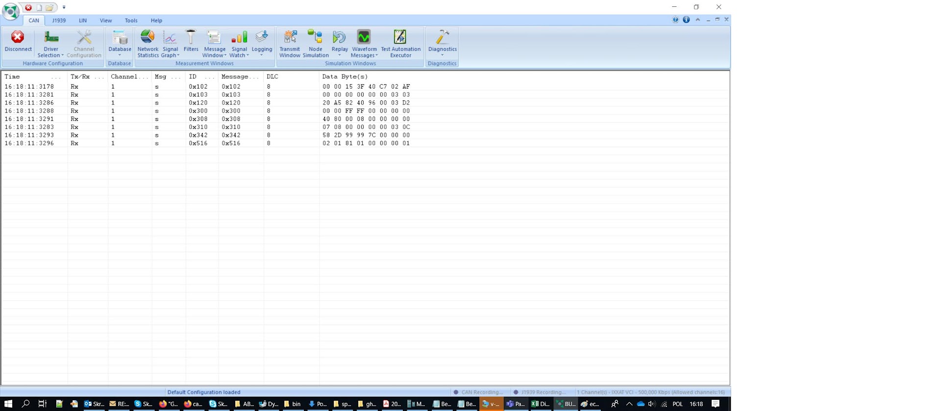
This for example is only ECU transmission without anything other connected.
ACtC-3cuPjcz2KkQDaRetUEtEXZPeU30PAp13_1Z3hlBf9ovzzqCoo9ghHxIuP5lKHToaWImdWWw2yt22n707U0pI6-Z5hdfFbPgsbtvp6wOvFSyeUqCUg3EbiIMy4FPl-wI8eMmQYyzkx4AAv0SvZMDqPK8=w1922-h839-no


Some messages are static, some change a little, most of them have counters as byte 6 or 7. Busmaster will write something like this:

17:31:34:1476 Rx 1 0x120 s 8 00 00 53 41 96 00 01 85
17:31:34:1479 Rx 1 0x300 s 8 00 00 FF FF 00 00 00 00
17:31:34:1481 Rx 1 0x308 s 8 40 80 00 00 00 00 00 00
17:31:34:1484 Rx 1 0x342 s 8 58 2D 00 00 7D 00 00 00
17:31:34:1486 Rx 1 0x516 s 8 02 01 81 01 00 00 00 01
17:31:34:1489 Rx 1 0x102 s 8 00 00 15 3E 3F C8 01 DD
17:31:34:1491 Rx 1 0x103 s 8 00 00 00 00 00 00 01 01
17:31:34:1494 Rx 1 0x310 s 8 87 00 00 00 00 00 01 86
17:31:34:1496 Rx 1 0x120 s 8 00 A5 53 41 96 00 02 23
17:31:34:1498 Rx 1 0x300 s 8 00 00 FF FF 00 00 00 00
17:31:34:1501 Rx 1 0x308 s 8 40 80 00 08 00 00 00 00
17:31:34:1503 Rx 1 0x342 s 8 58 2D 00 00 7D 00 00 00
17:31:34:1506 Rx 1 0x516 s 8 02 01 81 01 00 00 00 01
17:31:34:1586 Rx 1 0x102 s 8 00 00 15 3E 3F C8 02 DE
17:31:34:1589 Rx 1 0x103 s 8 00 00 00 00 00 00 02 02
17:31:34:1591 Rx 1 0x310 s 8 87 00 00 00 00 00 02 85
17:31:34:1686 Rx 1 0x102 s 8 00 00 15 3E 3F C8 03 DF
17:31:34:1688 Rx 1 0x103 s 8 00 00 00 00 00 00 03 03
17:31:34:1691 Rx 1 0x310 s 8 87 00 00 00 00 00 03 84
17:31:34:1693 Rx 1 0x120 s 8 20 A5 53 41 96 00 03 02
17:31:34:1696 Rx 1 0x300 s 8 00 00 FF FF 00 00 00 00
17:31:34:1698 Rx 1 0x308 s 8 40 80 00 08 00 00 00 00
17:31:34:1701 Rx 1 0x342 s 8 58 2D 00 00 7C 00 00 00
17:31:34:1703 Rx 1 0x516 s 8 02 01 81 01 00 00 00 01
17:31:34:1786 Rx 1 0x102 s 8 00 00 15 3E 3F C8 04 D8
17:31:34:1789 Rx 1 0x103 s 8 00 00 00 00 00 00 04 04
17:31:34:1791 Rx 1 0x310 s 8 87 00 00 00 00 00 04 83
17:31:34:1886 Rx 1 0x102 s 8 00 00 1A 3E 3F C8 05 D6
17:31:34:1888 Rx 1 0x103 s 8 00 00 00 00 00 00 05 05
17:31:34:1890 Rx 1 0x310 s 8 87 00 00 00 00 00 05 82
17:31:34:1894 Rx 1 0x120 s 8 20 A5 53 41 96 00 04 05
17:31:34:1896 Rx 1 0x300 s 8 00 00 FF FF 00 00 00 00
17:31:34:1899 Rx 1 0x308 s 8 40 80 00 08 00 00 00 00
17:31:34:1901 Rx 1 0x342 s 8 58 2D C3 03 7A 00 00 00
17:31:34:1903 Rx 1 0x516 s 8 02 01 81 01 00 00 00 01
17:31:34:1986 Rx 1 0x102 s 8 00 00 34 3E 3F C8 06 FB
17:31:34:1988 Rx 1 0x103 s 8 00 00 00 00 00 00 06 06
17:31:34:1991 Rx 1 0x310 s 8 87 00 00 00 00 00 06 81
17:31:34:2086 Rx 1 0x102 s 8 00 00 4F 3E 3F C8 07 81
17:31:34:2088 Rx 1 0x103 s 8 00 00 00 00 00 00 07 07
17:31:34:2091 Rx 1 0x310 s 8 87 00 00 00 00 00 07 80
17:31:34:2093 Rx 1 0x120 s 8 20 A5 83 41 96 00 05 D4
17:31:34:2096 Rx 1 0x300 s 8 00 00 FF FF 00 00 00 00
17:31:34:2098 Rx 1 0x308 s 8 40 80 00 08 00 00 00 00
17:31:34:2101 Rx 1 0x342 s 8 58 2D C3 03 7C 00 00 00
17:31:34:2103 Rx 1 0x516 s 8 02 01 81 01 00 00 00 01
17:31:34:2186 Rx 1 0x102 s 8 00 00 5D 3E 3F C8 08 9C
17:31:34:2188 Rx 1 0x103 s 8 00 00 00 00 00 00 08 08
17:31:34:2191 Rx 1 0x310 s 8 87 00 00 00 00 00 08 8F
17:31:34:2286 Rx 1 0x102 s 8 00 00 63 3E 3F C8 09 A3
17:31:34:2288 Rx 1 0x103 s 8 00 00 00 00 00 00 09 09
17:31:34:2290 Rx 1 0x310 s 8 07 00 00 00 00 00 09 0E
17:31:34:2294 Rx 1 0x120 s 8 20 A5 83 41 96 00 06 D7
17:31:34:2296 Rx 1 0x300 s 8 00 00 FF FF 00 00 00 00
 
Last edited:
I've finished bleeding brakes. I tried twice because first time, even with buds and vacuum it wasn't successful. I've forgot to unbolt front brake calipers and put them so that bleeder is above brake lines. With that approach buds was not needed for removing air from lines.

I've checked BLS and pressure sensor - all seems ok. Unfortunatel after few meters of ride again there is error C0044 which indicates problem with ABS pressure sensor or brake light switch. I've started engine again and no problem. On Buds error has occured but nothing else. BLS working, pressure ok. No other errors regarding communication issues or anything else.

ACtC-3fzJvb4GMh3_8kOYwkP8PM2ZzS5LhsM-B9btpmkhKpQrAtNNvZ6fxfzg6BU8FOFgxB2agyghQ3PrWLKWMjtvpRAU7H5rRVxdRH7J4IRCtlRFGFDqAQaimGqDmYNK2GI0xtKsP75PdsbXfzLLr-hexMn=w1579-h888-no


I have no idea what is going on. Maybe there is a problem because BLS is coming when pressure is too low, maybe brake light should come out above ex. 500kPa, or it is other way around. Right now my BLS activates when 200kPa is already applied to brakes.
Actually, when I think about it, BLS should come out before any pressure reading, otherwise it doesn't make sense. There should be indication that braking is applied before actual braking happens. Maybe this is a problem.
Does anyone could check their kPa reading when brake light is activated?
 
Belt tension could be checked with something as simple as fishing scale. According to someone from the forum 4,5kg should cause deflection of 18mm at center of the belt.

ACtC-3fJWFV6cV58xQLoMPaHdd_a5ayPIeLcuyKRFLbs-FvPbCCYN0K-zPYrnoGIhJsWXufpv3-X8tYyCAxJW6-0tWEezV-eDrUKMgPh4leR3mTljYjhXdFRCYdsk-GLe-zlNgN28vdBjQcJolsnP0acP35_=w696-h927-no


I've painted my steering rods which were fabricated from steel precision pipe and parts made for can am outlander G2. Cost me 50$ to make both left and right side.

ACtC-3ewXgsaJ_KNw4JXsMp_zZNhOVt6H3S-5LZmKEHlLZ8_mYzLTTjvX3k2OAT4Gi3jiDjktmbR1wA9hsQp2j2u-iSJGfKmWF6_DIYC3XtuNKo4BHFbRw0EKbXmm5QWqgoXomSUIfq-Dpynw0SHqjS2XgNd=w696-h927-no


Lots of parts are missing unfortunatel. I still need to made mounts for stabilizer bar. I was surprised that oem links for stabilizer bare are made from plastic. They could be changed very fast using heim joint rod ends but for now I'm keeping this plastic.

Does anybody know what is this below? It looks like steel strap for ground but it is definetely not that. Maybe something to stop suspension from from going too much down like in racing prerunner trucks ;).

ACtC-3c4wPYvMsJjWNOR5jVluzaEQD_rN4_7Nd41hkh3OqFvLGQ9zCul4bFJp3GTYH6oSIU_9jNxBO35HrwoW5s9mbu9eUs5hn0VTB15R1180_dNVk08oksVZyG98JSNTcY12bX3Z95zGGC1AZtxzVeLrsLu=w696-h927-no
 
.......
Does anybody know what is this below? It looks like steel strap for ground but it is definetely not that. Maybe something to stop suspension from from going too much down like in racing prerunner trucks ;)
.......

The Spyders use their rear shock as the 'limiting strap', so it's not one of those! :lecturef_smilie:

However, I reckon it looks a helluva lot like the 'earth strap' for the radio antenna! :thumbup: The RT's had their antenna high up there well clear of any real 'metal ground plane' on the back alongside the lid of rear trunk & behind the pillion 'arm-rest' - well, those pads where a pillion passenger might be tempted to put their elbows anyway.... IF they can get them on there! :p

Sounds (& from the pics, looks like it too! :rolleyes: ) like you're having a lotta fun doing this Mega ;) Good stuff, keep on at it! :2thumbs: Watching your progress with much interest. :clap:

Thank you, I couldn't figure out what it is. That is exactly ground for antenna as seen on "Electrical Accessories 3" schematics in parts catalogue. I don't have antenna though, or radio. All lost. I have CB module and I don't know what to do with it :P.
I will probably use one of round marine radios when I'll be making my cargo harness but there is not much space in front for that. Oh, will see.
 
Does anybody know what is this below? It looks like steel strap for ground but it is definetely not that. Maybe something to stop suspension from from going too much down like in racing prerunner trucks ;).
I think it is in fact a ground strap, probably to the radio antenna. Did by chance the bike have a CB? If so it probably is the ground strap for the CB antenna.
 
I just saw your comment about the CB module. You'll just have to toss it in the trash unless you install an OEM radio. As far as the radio goes, it was controlled by the left handlebar controls via CANbus so if you do use a marine radio you'll have to figure out some other way to control it.
 
I just saw your comment about the CB module. You'll just have to toss it in the trash unless you install an OEM radio. As far as the radio goes, it was controlled by the left handlebar controls via CANbus so if you do use a marine radio you'll have to figure out some other way to control it.

I'm in struggle here. I have option to buy used radio but it will be more expensive than new branded marine radio. And I don't have radio controller for passenger. And oem radio only has ... radio, right? Marine solutions have already built-in options to use bluetooth, usb, spotify etc. But, no remote control through cable, only remote pilot which passenger will lose in no time. Or, i need to 3d print housing for the pilot and that would actually work fine.

Another problem is, as you said, no control through multiswitch. Creating can reader for radio and controlling it that way would be PITA. I've never had radio on my bikes before, so I'm not convinced it is so important to have it, or even have control through multiswitch. I need to put something there, start using it and check afterwards what is working for me and what I want to change. Now it is only theory if I'm not riding.
 
The OEM radio has several world region options but I don't know what happens with all the bands when a region other than US is selected. The US bands are FM, AM, iPod, Aux, Weather, and CB if a CB is connected. In the grand scheme of FM radios, the BRP radio's ability to clearly pull in stations has been the subject of much criticism. If for you a radio is low priority then go with the marine radio, or even rely on the radio in Bluetooth helmet headsets. Your other challenge will be to find a usable place to mount a marine radio if you need to access its front panel controls. The OEM is mounted under the right side body panel under the passenger hand grip.
 
The OEM radio has several world region options but I don't know what happens with all the bands when a region other than US is selected. The US bands are FM, AM, iPod, Aux, Weather, and CB if a CB is connected. In the grand scheme of FM radios, the BRP radio's ability to clearly pull in stations has been the subject of much criticism. If for you a radio is low priority then go with the marine radio, or even rely on the radio in Bluetooth helmet headsets. Your other challenge will be to find a usable place to mount a marine radio if you need to access its front panel controls. The OEM is mounted under the right side body panel under the passenger hand grip.

I appreciate your help, it allows me to have better understanding of the system.

Having some space for radio is my biggest issue. I don't see any place to do that, especially if radio will be with built-in amplifier. Also, branded marine radio is usually quite expensive and this is another problem.

Another option is to buy small class D amplifier, put it where oem radio was and allow connection through jack audio connector in front and back. That would allow to use MP3 player or bluetooth transmitter for cars both for driver and passenger. I could also use phone connected through jack and buy cheap 5$ bluetooth controller mounted on steering wheel. Loosing that would not be an issue.
I think I will go that route since there is no space for marine radio.

BTW there is a solution for F3 to put radio controller in center of handlebar and amplifier in front trunk. This makes sense because controller itself is small and big amplifier is hidden.

Thanks again :)
 
New item installed (20$). Hawing only on/off sensor for oil pressure is not enough for me and I need to fill empty space after I douldn't find coolant temperature gauge.
I've installed pressure gauge used on old tractors. It idicated almost 5 bar - quite a lot. Thread in engine case is M10 x 1.
For coolant temperature gauge I will have to check what voltage for which temperature is output from cluster and buy something smaller or place it instead of fuel gauge.

ACtC-3dsHU8sTJgUhzq6Sr-G5j8ODFRnKcYAlO_m6CEKRoUbCusysqdX_LAgWC8y_WCTEAoEBYVvId2LMd4mpgLXCFu_ganMoqUyHXWoJmAJFCaprkW74EMYOw1gt5lo3bVZX7yXUV8hgku6a8sMhdESPBeB=w696-h927-no

ACtC-3eb2-jixHr7-BGenAYrH2M3ysDw18FOKnb2vW_NuA3jv5QPrVMPT3OTpFH6F_nklXe9x5NTObtA_uIJeliz6zUX1zejhAGebxNeCTKGkHdx0EgvDhbSezXfnQnBmb6jE868DZzI11E6mhdkSDtGS_Y0=w696-h927-no


There are two types of Y connectors for additional "sensor". I have the one which may require additional shims between connector and engine to allow proper positioning of additional hose for oil pressure monitoring.
Another type is something like this below and does not require any additional work to fit.

ACtC-3dz-i7t_6HrKDBCQyVShVrZOGpFT1b5ITG6rVIDvNMuAa1PySJiNa-PQznPQ1tYaW2Wy5AtZLm0h_N_HDIZrMT2Asf7K4Qj7cAUuOYiB3vLirf3NFxuidxdAQt74pM9abz9jwi-h4K7oTtunWWnk4V3=w800-h480-no


Remember that working pressure is 5 bar at least. I don't know how far it will go during heavy runs. As I remember max is around 6 bar according to can am specification.
 
I've started working on cargo harness. It is a little bit tough not to mess up proper placing of connectors.

I've added cables to connect additional blinkers on each side of cargo lid. I don't know how blinking frequency will be affected when additional parallel led light will be introduced. Worst case scenario - I will not use it or I will have to add additional resistors in series with new lights to keep resistance of whole system at same level.
It might sound strange but adding new lights may cause faster blinking because parallel connection lowers resistance of electrical loop.

ACtC-3evZqGzzSYrPvB_15jrv_kKj56xIcFzvL73lr2IEx10HH-dd-a4HKIBblDRe9V2YAbtfjMoo19-jJMGQkC8HtQuwoboL26D1cAMOGI5WogXbCo9VjJndiKrv7i5oftupCiwiWhTuW21ohR1ss_VFyyx=w1236-h927-no


When connecting 2 cables together I did not use soldering - only crimping. This will not deteriorate the cable and soldering may fail if you are not skilled enough (cold joints are your enemy). And crimping is much faster.

ACtC-3cwR_BCU_UBkDl5WMeXUvIjDiJ712qzXJ62I8FpA3y_Vak5R34MiPxkfDxkZKsAE8IwNwrRx4bKSzdpjjo7LK7p0ZQAlkw6_e9zGoJqXnQKh23VyGSti0j9TcHcfI7tG6bH1Y49VSXMuFhmaeM5TrBH=w1236-h927-no


I also added connector for heated seat which was sold to me with can am. It uses same relay as heated grips so that turning off my spyder will not drain battery if someone will forget to turn off heating.
 
I've modified mounts for standard radio to accomodate new amplifier. With heated knife I've cut gaps in this big plastic part from under seat to slide amplifier's mounting plate in. With straps and additional screw it holds very tightly.

ACtC-3cDtl96WBBfmmP8jwl0IE81LFgVIqXIqdd3xTkczOF_lm9aJ6aEJIWe5RXlHwiLcO3j6pXpJ-6oDSDH9zTxJD8fqsXrzx6TLPjq8DwAGcKuEbtQPMFbRdvG2XaoK2iR0yvQr_9sHqhCR9QEcr2aVj15=w1236-h927-no


ACtC-3cOrwtdh8pnlU_P1FQZeyq6lBXnwG3o-hxIVftLQpDhw7-zHsv9jU6pPxq4jKJGNGnl6k7Rkr2t7rdF-VCsgKz_u-thfOq8TeQuD73YpyybhwJdg13HfnvXG6ItFsMZmNeJEi95evylXQsp0rjwXWnv=w1236-h927-no


I have a small favour for someone with automatic rear air shock adjustment. I don't have a switch and I'm not sure which one I should buy.
Is up/down swich for compressor a momentary switch for both up and down option?
If one of rear cases is opened will suspension go up or down?
When going up/down with one of rear cases opened, will opened state be indicated in cocpit?


Schematics are showing something strange.
2 and 6 goes to cocpit.
3 - case switches resistor
1 - "down" resistor
5 - "up" resistor

Free and Up option seems to check whether rear cases are opened, but not Down option. It doesn't make sense.
Either case switches are always active, and then it doesn't make sense to connect them through compressor swich, or they are not active when up/down is pressed.

ACtC-3er_6R69bN3EVR1dDER9HuffeJTceKRXfcFu_KqO6czWAsy-8y48yGCYX6pcXTRRO8UyTOrUiYRu58QA1iIjSvNddC3ZOs5sZ2OsdG8254U_TC1oV7sfkiAKVEsmVpqjaBNJtdQZHnaBaUsddav3Zcl=w265-h346-no
 
I've bought this one for 2,5k USD. My goal was to keep within 5k USD but ABS unit did not allow that. :)
To be honest when I bought this spyder I didn't know how many things could fail because of bad engineering. Normally I don't use cars/bikes with too much electronics. I have older Hilux, Honda from 93 and old bikes like KLX 650 from 94. They all run great. If something happens you can fix them with simple tools. This is not the case with spyder and this is bad judgement from my side. But, I still want to learn how things are done and want to be first to fix problems which are giving people headache.

Also, I hate when things (expensive and cheap) are thrown to garbage.

Great project, thank you for your contribution to the community.

I understand almost none of it but I'm reading with fascination anyway.
 
Last edited:
I have a small favour for someone with automatic rear air shock adjustment. I don't have a switch and I'm not sure which one I should buy.
Is up/down swich for compressor a momentary switch for both up and down option?
If one of rear cases is opened will suspension go up or down?
When going up/down with one of rear cases opened, will opened state be indicated in cocpit?


Schematics are showing something strange.
2 and 6 goes to cocpit.
3 - case switches resistor
1 - "down" resistor
5 - "up" resistor

Free and Up option seems to check whether rear cases are opened, but not Down option. It doesn't make sense.
Either case switches are always active, and then it doesn't make sense to connect them through compressor swich, or they are not active when up/down is pressed.
What year is the RT you're working on? If you mentioned it I can't find it. How about adding it to your signature block? The wiring diagram for 2010 is different from the one you show. The 2014diagram is the same as what you show except Up is Hard and Dwn is Soft. On the 2010 the circuit from pin 3 is closed to ground only when the switch is in the Free position and a case lid is open. In 2010 each case switch has a resistor across the switch but for 2014 there is one resistor in that line ahead of all three case switches. So for 2010 the case switches have no affect when choosing either hard or soft. For 2014 they would have an affect only when Hard is pressed. Pin 2 & 6 go to the cluster so obviously the cluster monitors the current draw through that line to determine what action is to be taken.

The switch is a double pole momentary on/off/momentary on configuration. That much I can tell you. I haven't checked if the lids being open affect the compressor operation or not, but I'm going guess right now, no. If you aren't aware the compressor will run, or the air relief valve open, only when the Spyder is running and in gear.
 
Back
Top