Hi there,
I'm installing a Rostra electronic cruise control on my wife's 09 SE5 (no clutch) and I'm ready to hook up the wires. I was hoping I could get some assistance from someone that has recently installed this unit.
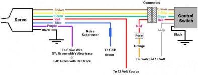
My Rostra servo has three additional wires that are not included in the diagram that is shown on this website.
I attached the diagram for convenience.
Specifically, I'm talking about an orange, light green and gray wire. According the the manual, the orange is for the ENO function (enable output). The green wire is for the Neutral Safety Switch. Both these wires are trimmed back and covered with electrical tape. The gray wire is for the VSS unless a magnet and coil is used, which I have. The manual states to trim the gray wire back to avoid stray signals. So, I assume that I won't be using the orange, light green and gray wire, correct ?
Per the website diagram the servo blue wire goes to the coil. I have a brown/orange and a brown/black wire going to the coil. Which one do I use. And just to be clear, I still need to run a wire to the coil even though I am hooking up the magnet and coil speed sensor, correct ?
The servo 4 pin connector that goes to the control pad has a green, yellow, red and a red/brown wire. The control pad wiring is black, gray, green, yellow, red and brown. I assume the the servo red/brown wire goes to the control pad brown wire, correct ?
The manual states that the servo red wire should go the "hot" side of the brake switch and the violet (purple)wire should go to the "cold" side of the brake switch. Does this really need to be hooked up like this ? The website diagram shows the red wire going to a 12 volt source and the purple wire going to the brake wire. Where did you hook up these wires ?
The other servo red wire and control pad gray wire goes to a switched 12 volt source. Where did you hook these up ?
Okay last question; where did you chose to ground your ground wires ?
Sorry about the question overload !
Thanks in advance,
Ray
I'm installing a Rostra electronic cruise control on my wife's 09 SE5 (no clutch) and I'm ready to hook up the wires. I was hoping I could get some assistance from someone that has recently installed this unit.
My Rostra servo has three additional wires that are not included in the diagram that is shown on this website.
I attached the diagram for convenience.
Specifically, I'm talking about an orange, light green and gray wire. According the the manual, the orange is for the ENO function (enable output). The green wire is for the Neutral Safety Switch. Both these wires are trimmed back and covered with electrical tape. The gray wire is for the VSS unless a magnet and coil is used, which I have. The manual states to trim the gray wire back to avoid stray signals. So, I assume that I won't be using the orange, light green and gray wire, correct ?
Per the website diagram the servo blue wire goes to the coil. I have a brown/orange and a brown/black wire going to the coil. Which one do I use. And just to be clear, I still need to run a wire to the coil even though I am hooking up the magnet and coil speed sensor, correct ?
The servo 4 pin connector that goes to the control pad has a green, yellow, red and a red/brown wire. The control pad wiring is black, gray, green, yellow, red and brown. I assume the the servo red/brown wire goes to the control pad brown wire, correct ?
The manual states that the servo red wire should go the "hot" side of the brake switch and the violet (purple)wire should go to the "cold" side of the brake switch. Does this really need to be hooked up like this ? The website diagram shows the red wire going to a 12 volt source and the purple wire going to the brake wire. Where did you hook up these wires ?
The other servo red wire and control pad gray wire goes to a switched 12 volt source. Where did you hook these up ?
Okay last question; where did you chose to ground your ground wires ?
Sorry about the question overload !
Thanks in advance,
Ray