• There were many reasons for the change of the site software, the biggest was security. The age of the old software also meant no server updates for certain programs. There are many benefits to the new software, one of the biggest is the mobile functionality. Ill fix up some stuff in the coming days, we'll also try to get some of the old addons back or the data imported back into the site like the garage. To create a thread or to reply with a post is basically the same as it was in the prior software. The default style of the site is light colored, but i temporarily added a darker colored style, to change you can find a link at the bottom of the site.

Relays

JerryB

New member
Hi folks,

I am going to be doing some new wiring on my Spyder and have been looking for Normally Closed Relays.

I usually buy my relays from Eastern Beaver because he sells good stuff:

https://www.easternbeaver.com/Main/main.html

However, he does not carry a Normally Closed Relay.

After a lot of time on the 'net, lots of emails, too many phone calls, I found this:

https://www.alliedelec.com/schneider-electric-magnecraft-92s11d22d-12/70185037/

And what is even better is that it can control two seperate lites seperately.

Now, I have not yet gotten this little guy here to actually try/use; I'll try to keep you posted on how it works.

Just some info for those nutty DIY'ers like me,

Jerry Baumchen

PS) Here is a sketch of what I am trying to do:

MC Lites.jpg
 
I'm with him...

:agree: not totally sure what the plan is....If they are that hard to find must not be used that much....:dontknow: like eastenbeaver.....:thumbup:
 
Unless I am not reading you right, you are looking for normally closed relays.
Why normally closed? Most general market relays are of the open contact variety
of a 30 amp rating and closed when you apply power to the coil of the relay. This in
turn applies power to one or 2 output terminals to switch something on. Normally
closed relays would require a constant power source to keep the relay open and break
the flow of power. Please keep us posted as to what you have going on. My curious Pea
brain would like to know.

Thanks in advance

Dray :yes::yes::yes::yes:
 
Hi Dray,

Re: you are looking for normally closed relays. Why normally closed?

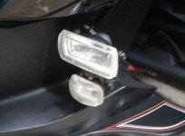
Gene De Laney ( Chupaca ) on here added these lites to his Spyder, they mount onto the sides of his frunk:

Spyder lites.jpg


Gene controls his with an On/Off switch mounted on his handlebars.

I am wanting to add one driving lite to each side of my Spyder at the front as Gene has done.

However, I do not want to have to use a On/Off switch; too easy IMO to forget resulting in a dead battery

1. Look at the sketch in my OP - I will come from the battery ( power from the battery, not from anything else that might upset the CanBus on the Spyder ) to an in-line 3 amp fuse ( protection for the lites ), then to a Normally Open Relay - This N O relay will be tripped by somewhere on my Spyder by power that only comes on with the key; probably grab this tripping power from the headlite wiring. This keeps the driving lites on when I am out riding around yet turn them off when I shut down the Spyder; which is what I want.

2. Then the power will go from the N O relay to the Normally Closed Relay ( I found one that is a single relay that can control two circuits individually ). Then I will bring two tripping wires from my existing turn signal circuits; these will then open either side of the N C relay, thereby interrupting the power to the driving lites and making them into additional turn signals.

Does that make sense to you?

If not, let me know & I'll give it another try.

Jerry Baumchen

PS) The human species can be very inventive. Plus, I like thinking outside of the box.


Ahhh Brilliant!

Hi Dray,

Re: you are looking for normally closed relays. Why normally closed?

Gene De Laney ( Chupaca ) on here added these lites to his Spyder, they mount onto the sides of his frunk:

View attachment 153676


Gene controls his with an On/Off switch mounted on his handlebars.

I am wanting to add one driving lite to each side of my Spyder at the front as Gene has done.

However, I do not want to have to use a On/Off switch; too easy IMO to forget resulting in a dead battery

1. Look at the sketch in my OP - I will come from the battery ( power from the battery, not from anything else that might upset the CanBus on the Spyder ) to an in-line 3 amp fuse ( protection for the lites ), then to a Normally Open Relay - This N O relay will be tripped by somewhere on my Spyder by power that only comes on with the key; probably grab this tripping power from the headlite wiring. This keeps the driving lites on when I am out riding around yet turn them off when I shut down the Spyder; which is what I want.

2. Then the power will go from the N O relay to the Normally Closed Relay ( I found one that is a single relay that can control two circuits individually ). Then I will bring two tripping wires from my existing turn signal circuits; these will then open either side of the N C relay, thereby interrupting the power to the driving lites and making them into additional turn signals.

Does that make sense to you?

If not, let me know & I'll give it another try.

Jerry Baumchen

PS) The human species can be very inventive. Plus, I like thinking outside of the box.


So one light is on 100%, other blinks; or one light that also blinks. Great idea! Yes, tapping the blinker & headlight wires to drive the coils of a relay is super safe - I chose the relay version of the trailer wiring kit for the same reason.
 
Hi Alaska,

Re: Above my pay grade.

It was for me also before I learned enough to be dangerous. :yikes:

I'll take a go at explaining relays to you. If anyone here thinks any of this is wrong, jump in as I am no expert.

About 20 yrs ago I put in a new garage door opener. The lite that was built-in on the garage door opener was a 60 W bulb & it only would lite up ( somewhat ) the front of the garage, the area from the motor/lite on the opener towards to garage door. The rest of the garage was quite dark. This 60 W lite bulb stays on for about 3 minutes whenever the garage door opens or closes.

I dug into the tech info ( I'm a ret'd Mech Engr ) for the garage door opener & started reading. It said to never replace the 60 W bulb with a bigger bulb because the circuit could not handle the additional load.

So I bought a relay & located it up above the sheetrock in my garage.

I brought 110 V power in from somewhere in the house; a constant power source.

I then added two large flood lites to the area of my garage that was not lit by the little 60 W bulb.

So now, I have 110 V power coming into my relay & going out to the two floodlites, when the relay is tripped & only when it is tripped.

Then I tapped into the 60 W lite bulb circuit ( a fairly simple soldering job ) and ran this wire to my relay; this is the tripping wire. It sends a very low voltage signal to the relay.

So now when I pull into my garage, the 60 W bulb lites up & my two floodlites also lite up; all for the 3 minutes that the garage door circuit tells them to.

Does this help explain what a relay does?

Jerry Baumchen

PS) What I call the 'tripping' wire some people will call a 'control' wire; different strokes for different folks.
 
Hi Steve,

Re: So one light is on 100%, other blinks; or one light that also blinks.

No. Both driving lites are on when the key switch turns them on & they stay on while just driving down the road.

Then when either turn signal is turned on, the Normally Closed Relay for that lite becomes open, turning that driving lite off. It ( hopefully ) will blink On - Off, but just the opposite of the turn signals.

Does that make sense to you?

Re: Great idea!

Well, I like to think so. We'll just have to see how it works when I get everything installed; just waiting on the N C relay to arrive.

Jerry Baumchen
 
Hi Gene,

Re: If they are that hard to find must not be used that much....

Actually, a single Normally Closed Relay is almost always a Normally Open Relay also. It just performs either duty depending upon how you connect the various wires to it.

I found a single relay that can control two seperate circuits, that was the hard item to find.

I could have bought two relays, one for each driving lite but that would be more bulk. I plan to put this Normally Closed Relay right behind my instrument panel, so I did the extra work to find a single unit that ( hopefully ) will control both driving lites.

That's my story and I'm sticking to it,

Jerry Baumchen
 
Transistor Switch

Hi Dray,

Re: you are looking for normally closed relays. Why normally closed?

Gene De Laney ( Chupaca ) on here added these lites to his Spyder, they mount onto the sides of his frunk:

View attachment 153676


Gene controls his with an On/Off switch mounted on his handlebars.

I am wanting to add one driving lite to each side of my Spyder at the front as Gene has done.

However, I do not want to have to use a On/Off switch; too easy IMO to forget resulting in a dead battery

1. Look at the sketch in my OP - I will come from the battery ( power from the battery, not from anything else that might upset the CanBus on the Spyder ) to an in-line 3 amp fuse ( protection for the lites ), then to a Normally Open Relay - This N O relay will be tripped by somewhere on my Spyder by power that only comes on with the key; probably grab this tripping power from the headlite wiring. This keeps the driving lites on when I am out riding around yet turn them off when I shut down the Spyder; which is what I want.

2. Then the power will go from the N O relay to the Normally Closed Relay ( I found one that is a single relay that can control two circuits individually ). Then I will bring two tripping wires from my existing turn signal circuits; these will then open either side of the N C relay, thereby interrupting the power to the driving lites and making them into additional turn signals.

Does that make sense to you?

If not, let me know & I'll give it another try.

Jerry Baumchen

PS) The human species can be very inventive. Plus, I like thinking outside of the box.


Jerry,
I cobbled up a transistor circuit that does what you are attempting with relays.
I use it for running my saddle bag LED lights as running lights, brake lights and turn signals.
The LEDs are on all the time except when interrupted by the turn signal power.
Then the LEDs flash opposite of the turn signals.
Less than $5 in parts and very little space. Best of all it doesn't mess with the Canbus.
PM me and I will send you a copy of my circuit diagram. No I'm not an electrical designer, just a DIYer.
My circuit values are probably overkill but it works.
Cheers, David C.
 
Hi David,

Re: Less than $5 in parts and very little space.

1. Building a circuit board is WAAAAYYYYYY over my pay grade.

2. It turns out that the relay supplier has taken mercy on me & are providing it for free.

Sometimes it helps to be a little charming when talking to women on the phone. :yes:

Jerry Baumchen

PS) Could you post up some info on how you designed it? That might help the other nutty DIY'ers on here.

PPS) Offers like this is why I really like this website.
 
Last edited:
Hi Steve,

Re: So one light is on 100%, other blinks; or one light that also blinks.

I just realized what you were referring to with this.

As shown in the photo, Gene has two lites on each side of his frunk.

I am installing just one lite on each side of my frunk. Ergo, both lites on all the time with one getting interupted when the specific turn signal is activated.

Jerry Baumchen
 
Hi Bill,

Re: You can get . . .

As I mentioned in Post #9:

Actually, a single Normally Closed Relay is almost always a Normally Open Relay also. It just performs either duty depending upon how you connect the various wires to it.

I found a single relay that can control two seperate circuits, that was the hard item to find.


I know that I could easily buy two relays but I found a single relay to control both lites. That was the gist of my OP.

Jerry Baumchen
 
You want relays

I get most of my relays for my work applications through Grainger. They have them in any voltage and configuration you would want.
 
Hi Bob,

Re: Pretty crafty, mister!

Let's not get ahead of ourselves. The mfr says it will do what I am wanting. When I get the relay & get it wired in, then I'll know if this idea is worth anything.

I'll try to keep this thread updated as things go along,

Jerry Baumchen

PS) From Post #5: I like thinking outside of the box.

Trying new things to see if they will work or not is what makes life interesting.
 
Last edited:
Hi Cabinkids,

Re: I get most of my relays for my work applications through Grainger. They have them in any voltage and configuration you would want.

Many, many years ago, a good friend worked at the local Grainger outlet. That is how I began dealing with them.

I have bought a 'fair' amount of stuff from Grainger over the years.

I could not find the relay that I wanted at Grainger. They might have one like it but I could not find it & they could not put me onto one.

IMO Grainger is a very good company; no complaints with anything that I have ever bought from them.

Jerry Baumchen
 
Now that I get what you want - this is it!

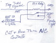
You guys are making this way to complex. You can get those cheap 12vDC relays that are single pole double throw: http://www.ebay.com/itm/5-sets-40A-...05&rk=1&rkt=1&&_trksid=p2045573.c100505.m3226

I used these to make my fender LEDS flash as turn signals, here is the schematic:

View attachment 153715

:agree: Almost. This circuit will flash the LED when the turn signal is ON. I think he wants to have a marker light that is ON all the time, that flashes during the turn signal. Seems like moving the "hot to fender lights" on the right side to the N.C. position fixes it. The light is ON all the time, then turns OFF when the turn signal is active. It will just blink out of sync - which looks cool! At least I THINK that's what he wants :dontknow:. It's what I would do - more lights the merrier!

Steve
 
Hi Steve,

Re: The light is ON all the time, then turns OFF when the turn signal is active. It will just blink out of sync - which looks cool! At least I THINK that's what he wants . It's what I would do

Yes, that is what I am planning doing.

Re: This circuit will flash the LED when the turn signal is ON.

I read his schematic the same way.

Jerry Baumchen
 
Back
Top