WackyDan
New member
PC- 8 power Buss install from Eastern Beaver - Pictures included
So...
This was one of those projects that took too long.
Excuses as follows:
1. Winter
2. Back went out
3. Got sick
4. Scrapped the first wire harness I made and started over.
5. Work
However, now I'm laid off, and am catching up on a ton of stuff. Sorry for the long ramble here, but hopefully someone finds it useful.
I bought an Eastern Beaver PC-8 from http://easternbeaver.com/Main/Products/Fuseboxes/PC-8/pc-8.html It is a quality product, and does a simple task very well. You can cob together something similar, but after looking at what was available over the counter and other similar products on the web, I felt the PC-8 was the best for my application.
I decided not to order a pre-made harness from Eastern Beaver. I just didn't see how any of those lengths would potentially be perfect for anywhere I wanted to mount this. That said, Jim at Eastern Beaver is very responsive to email, and it only took a weeks shipping from Japan to receive everything. Jim can make you a custom harness using your measurements. If you don't mind paying a premium and you don't have your own crimper or care to own one, that is the way to go. For me, it was cheaper to do it myself, except that I had to buy a new crimper! ( the one I had for many years vaporized - watch it show up now ) I bought:
Eastern Beaver:
- The PC-8,which comes with the open barrel terminals you need, heat shrink, and fuses. These take care of everything only at the buss. You still need some of the stuff below.
- Various additional open barrel terminals I wanted for the install as well "mistakes"
- An open barrel crimper - Really cheesed as I "used" to have one. I ordered this one stateside for about $70... Very handy to have.
- Fuse holders... Can buy these anywhere, but his prices were in line.
- Some heat shrink tubing from him - Had some, but he had the type with the glue inside which is nice for some connections.
- Relays and relay sockets.
- Some weather proof switches... He has some really nice ones.
- Asst other stuff - I tend to order more than I need of anything... I don't like having to shop twice.
Home Depot:
- I picked up some 12 gauge high heat, and abrasion/oil resistant stranded wire in Black, Red, and Yellow.
- Bought some 16 gauge stranded wire in Black for additional ground. I grounded the relays with this one straight back to the battery, and then looped it back into the PC-8... Not really necessary, but insurance never hurt.
- Bought some 16 gauge stranded wire in Blue for the trigger wire.
- Bought some 18 gauge stranded wire in White for the garage door opener. Side project -Has nothing to do with the PC-8 as it is run by it's own battery. It is a 12volt battery, so I could hook it into the PC-8 if I didn't mind the constant, if minimal draw.
Radio Shack:
- Diodes for the triggers
Tools and stuff used: (Beyond the standard hand tools)
-Paladin Crimpall 8026 crimper with 2033 open barrel die for 12 to 22 AWG wires and connectors. This did the job fairly well. On the heavy brass ring terminals for the battery, I had to use a woodworking clamp to get a real solid crimp. Otherwise, it was as good a tool that I used to have.
http://shop.willyselectronics.com/b...r-open-barrel-terminals-12-22awg-/4,1211.html
- 33 watt soldering iron. Probably hotter than most need, but nice when you want to fully heat a terminal quickly.
- Electric Heat gun or propane wide flame torch for heat shrink. I used the Tyco wide flame I already had, but most can get away with a bic lighter. http://mediafilms.org/cpg_web/CPGI_137.pdf
I originally made a harness that I chose to route from the battery under the seat/frame over to the back fuse bar... However, that didn't work so well. My thought was to have the fuse holders in that cavity near the other fuses, but it was too tight in that area. The loom plus wires was just too thick for some spots.
I re-grouped and re-made/adjusted the harness to run from the battery along the same side of the bike in the little nook along the tank and the backbone of the frame. I put the main fuses in the battery bay.
Now... I'm using two power leads which is the reason for the yellow and red wires. I wanted to differentiate them so I knew which one was for the switched and un-switched/constant circuit. They are each on their own 30amp mini blade fuse... That gives me roughly 360 watts per feed, though I'll never touch that. They are mainly there in case I have a short to ground. The PC-8 will provide the proper fuse sizing per circuit.
I'm a bit anal. I used to work on electronics at the system board level and have trouble shot, repaired, and built many a wire harness. Every open barrel crimp connector was also soldered... this prevents oxidation/corrosion in case they ever get damp or wet. I soldered splices rather than use crimp connectors for the same reason and that is another good reason for using the glue infused heat shrink. I encapsulated the harness in a large diameter length of regular heat shrink and shrunk it down. Made for a nice, easy to handle harness and added a bit of additional abrasion and heat protection. I then placed that in plastic wire loom. Again, the last thing I want is a direct short to ground.
I placed the PC-8 on top of the back bone, but under the fake tank tupperware. It just barely fits under there. I am mounting it with 3M auto trim tape leaving enough extra wire to make adjustments or future repairs. As you can see in the photos below, I mounted the relays on the plastic pegs holding the under seat shielding to the frame... Worked perfectly. Some Spyder Lovers have placed theirs behind the cluster, and that is a good spot too. I wanted to keep that area uncluttered as I may add HID's and the ballasts will go up there. The PC-8 is still easily reached where I have installed it. Two plastic rivets and two torx screws. I don't expect to be in there much if at all.
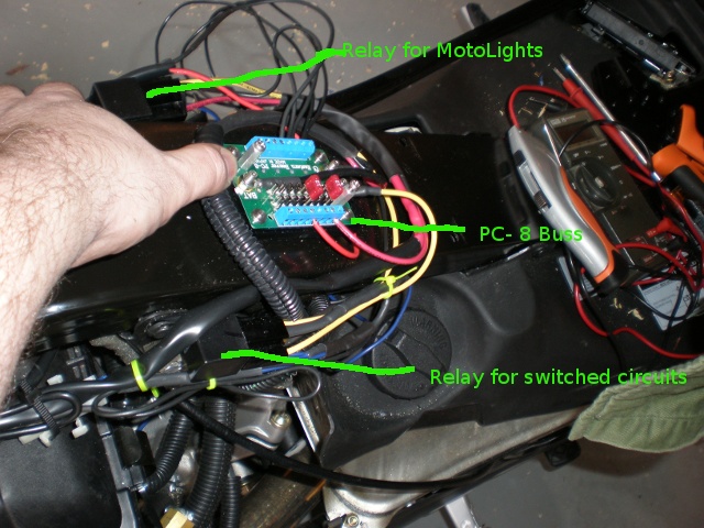
One relay is for the switched circuits. The other relay is for my Motolights. I did not want the motolights on by default all the time, so I needed to leverage a second relay. It is still on the switched circuit side of the PC-8, but triggered via an illuminated switch. Tell you what... I'm glad I did this, as the install of the motolights that was done at the Gatlinburg rally wasn't really ideal. This cleaned things up quite a bit and now I never have to worry about all the crazy crimps from that install going bad.
Finally, I have a diode in line with the trigger to each relay. This prevents any voltage back feed from the relay frying the computer. Supposed to be a rare failure, but 50 cents for insurance made a lot of sense. Jim points this out and goes into more detail on his site here: http://easternbeaver.com/Main/Products/Fuseboxes/Wiring_Kits/Diode/diode.html
Circuit usage on my Spyder:
Switched - Powerlets in dash and Motolights. Moto lights use 100 watts, or 8.33 amps, so there is plenty of overhead considering I'll only be running a GPS and/or phone off of the powlets on this circuit.
Unswitched - 12volt digital voltmeter, and powerlet in Helibars.
* I've got the voltmeter running though a push button switch so it is not on all the time.
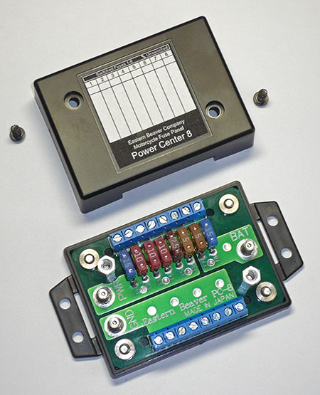
First... What the Eastern Beaver looks like (From Jim's site). Obviously one side is ground and the other is split between the 6 switched circuits (PWR on the board), and the two constant on circuits ( BAT on the board).
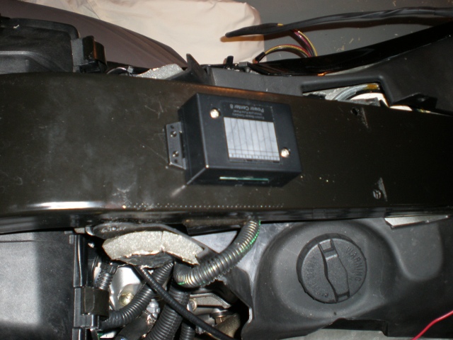
PC-8 sitting on my frame where it ultimately was installed:
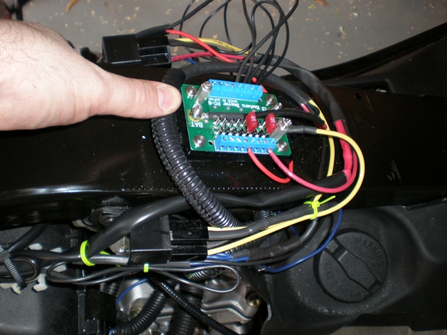
PC- 8 Wired up:
PC- 8 pic edited with pointers:
As you can see, I still have some tidying up to do. Tomorrow I finish installing my Helibar risers (write up coming on those), and wire in everything that is left and button her up. Then an oil change and some riding.
I also did the Garage door opener mod. I had a key chain door remote we don't use. So, I opened it up, removed one of the tactile button switches and soldered two wire leads to the board, then closed it back up after installing a new battery. I just used some velcro and stuck it up and out of the way behind the cluster. I used a momentary switch I bought from Jim@ Eastern Beaver to activate. I take pictures of where I put it tomorrow... Picture of the switch below... Really cheap, simple switch, and the boot anchoring it to the dash makes it weather proof... It also blends in with the dash so it isn't too obvious. Many thanks to those of you who already did this mod and gave me the idea too. More tomorrow in new thread.

So...
This was one of those projects that took too long.
Excuses as follows:
1. Winter
2. Back went out
3. Got sick
4. Scrapped the first wire harness I made and started over.
5. Work
However, now I'm laid off, and am catching up on a ton of stuff. Sorry for the long ramble here, but hopefully someone finds it useful.
I bought an Eastern Beaver PC-8 from http://easternbeaver.com/Main/Products/Fuseboxes/PC-8/pc-8.html It is a quality product, and does a simple task very well. You can cob together something similar, but after looking at what was available over the counter and other similar products on the web, I felt the PC-8 was the best for my application.
I decided not to order a pre-made harness from Eastern Beaver. I just didn't see how any of those lengths would potentially be perfect for anywhere I wanted to mount this. That said, Jim at Eastern Beaver is very responsive to email, and it only took a weeks shipping from Japan to receive everything. Jim can make you a custom harness using your measurements. If you don't mind paying a premium and you don't have your own crimper or care to own one, that is the way to go. For me, it was cheaper to do it myself, except that I had to buy a new crimper! ( the one I had for many years vaporized - watch it show up now ) I bought:
Eastern Beaver:
- The PC-8,which comes with the open barrel terminals you need, heat shrink, and fuses. These take care of everything only at the buss. You still need some of the stuff below.
- Various additional open barrel terminals I wanted for the install as well "mistakes"
- An open barrel crimper - Really cheesed as I "used" to have one. I ordered this one stateside for about $70... Very handy to have.
- Fuse holders... Can buy these anywhere, but his prices were in line.
- Some heat shrink tubing from him - Had some, but he had the type with the glue inside which is nice for some connections.
- Relays and relay sockets.
- Some weather proof switches... He has some really nice ones.
- Asst other stuff - I tend to order more than I need of anything... I don't like having to shop twice.
Home Depot:
- I picked up some 12 gauge high heat, and abrasion/oil resistant stranded wire in Black, Red, and Yellow.
- Bought some 16 gauge stranded wire in Black for additional ground. I grounded the relays with this one straight back to the battery, and then looped it back into the PC-8... Not really necessary, but insurance never hurt.
- Bought some 16 gauge stranded wire in Blue for the trigger wire.
- Bought some 18 gauge stranded wire in White for the garage door opener. Side project -Has nothing to do with the PC-8 as it is run by it's own battery. It is a 12volt battery, so I could hook it into the PC-8 if I didn't mind the constant, if minimal draw.
Radio Shack:
- Diodes for the triggers
Tools and stuff used: (Beyond the standard hand tools)
-Paladin Crimpall 8026 crimper with 2033 open barrel die for 12 to 22 AWG wires and connectors. This did the job fairly well. On the heavy brass ring terminals for the battery, I had to use a woodworking clamp to get a real solid crimp. Otherwise, it was as good a tool that I used to have.
http://shop.willyselectronics.com/b...r-open-barrel-terminals-12-22awg-/4,1211.html
- 33 watt soldering iron. Probably hotter than most need, but nice when you want to fully heat a terminal quickly.
- Electric Heat gun or propane wide flame torch for heat shrink. I used the Tyco wide flame I already had, but most can get away with a bic lighter. http://mediafilms.org/cpg_web/CPGI_137.pdf
I originally made a harness that I chose to route from the battery under the seat/frame over to the back fuse bar... However, that didn't work so well. My thought was to have the fuse holders in that cavity near the other fuses, but it was too tight in that area. The loom plus wires was just too thick for some spots.
I re-grouped and re-made/adjusted the harness to run from the battery along the same side of the bike in the little nook along the tank and the backbone of the frame. I put the main fuses in the battery bay.
Now... I'm using two power leads which is the reason for the yellow and red wires. I wanted to differentiate them so I knew which one was for the switched and un-switched/constant circuit. They are each on their own 30amp mini blade fuse... That gives me roughly 360 watts per feed, though I'll never touch that. They are mainly there in case I have a short to ground. The PC-8 will provide the proper fuse sizing per circuit.
I'm a bit anal. I used to work on electronics at the system board level and have trouble shot, repaired, and built many a wire harness. Every open barrel crimp connector was also soldered... this prevents oxidation/corrosion in case they ever get damp or wet. I soldered splices rather than use crimp connectors for the same reason and that is another good reason for using the glue infused heat shrink. I encapsulated the harness in a large diameter length of regular heat shrink and shrunk it down. Made for a nice, easy to handle harness and added a bit of additional abrasion and heat protection. I then placed that in plastic wire loom. Again, the last thing I want is a direct short to ground.
I placed the PC-8 on top of the back bone, but under the fake tank tupperware. It just barely fits under there. I am mounting it with 3M auto trim tape leaving enough extra wire to make adjustments or future repairs. As you can see in the photos below, I mounted the relays on the plastic pegs holding the under seat shielding to the frame... Worked perfectly. Some Spyder Lovers have placed theirs behind the cluster, and that is a good spot too. I wanted to keep that area uncluttered as I may add HID's and the ballasts will go up there. The PC-8 is still easily reached where I have installed it. Two plastic rivets and two torx screws. I don't expect to be in there much if at all.
One relay is for the switched circuits. The other relay is for my Motolights. I did not want the motolights on by default all the time, so I needed to leverage a second relay. It is still on the switched circuit side of the PC-8, but triggered via an illuminated switch. Tell you what... I'm glad I did this, as the install of the motolights that was done at the Gatlinburg rally wasn't really ideal. This cleaned things up quite a bit and now I never have to worry about all the crazy crimps from that install going bad.
Finally, I have a diode in line with the trigger to each relay. This prevents any voltage back feed from the relay frying the computer. Supposed to be a rare failure, but 50 cents for insurance made a lot of sense. Jim points this out and goes into more detail on his site here: http://easternbeaver.com/Main/Products/Fuseboxes/Wiring_Kits/Diode/diode.html
Circuit usage on my Spyder:
Switched - Powerlets in dash and Motolights. Moto lights use 100 watts, or 8.33 amps, so there is plenty of overhead considering I'll only be running a GPS and/or phone off of the powlets on this circuit.
Unswitched - 12volt digital voltmeter, and powerlet in Helibars.
* I've got the voltmeter running though a push button switch so it is not on all the time.
First... What the Eastern Beaver looks like (From Jim's site). Obviously one side is ground and the other is split between the 6 switched circuits (PWR on the board), and the two constant on circuits ( BAT on the board).
PC-8 sitting on my frame where it ultimately was installed:
PC- 8 Wired up:
PC- 8 pic edited with pointers:
As you can see, I still have some tidying up to do. Tomorrow I finish installing my Helibar risers (write up coming on those), and wire in everything that is left and button her up. Then an oil change and some riding.
I also did the Garage door opener mod. I had a key chain door remote we don't use. So, I opened it up, removed one of the tactile button switches and soldered two wire leads to the board, then closed it back up after installing a new battery. I just used some velcro and stuck it up and out of the way behind the cluster. I used a momentary switch I bought from Jim@ Eastern Beaver to activate. I take pictures of where I put it tomorrow... Picture of the switch below... Really cheap, simple switch, and the boot anchoring it to the dash makes it weather proof... It also blends in with the dash so it isn't too obvious. Many thanks to those of you who already did this mod and gave me the idea too. More tomorrow in new thread.
Last edited: