kevorama
MOgang Member & Pyro-Man
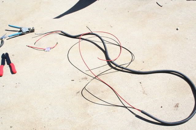
I pulled the frunk on Friday. The main reason was to install TricLED's FuzeBlock and my PSU/Receiver for my LED under lighting. The following is how it went down. The first thing I did was to make a 2 wire harness out of 12g stranded wire and armored plastic casing. Since I wanted an inline fuse as close to the + terminal as possible and accessible without removing panels I cut the inline fairly close to the fuse holder, stripped the wire, crimped a weather proof ring terminal and heat shrank it.
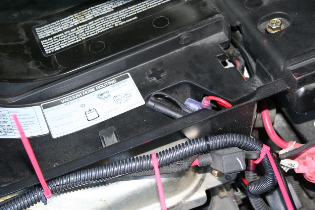
Here is a shot of where I can get to the fuse for replacement or trouble shooting.
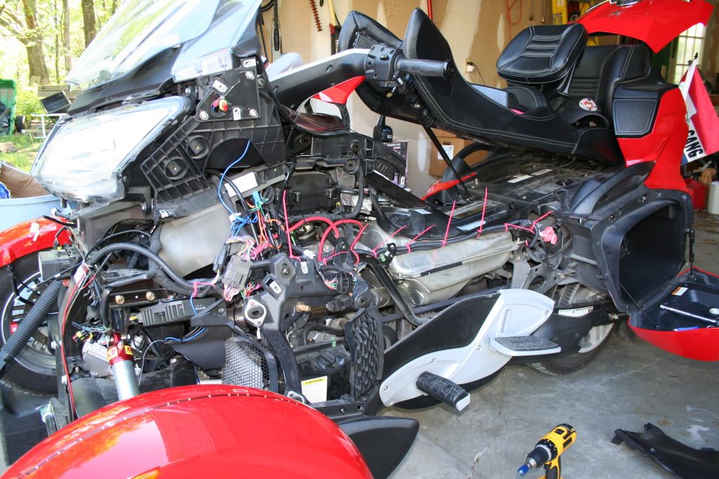
I left hot pink Zip Ties in place so that you could see where the new power lines were routed to the frunk. After getting into it, I realized that I wasn't comfy putting the FuzeBlock and the LED receiver in the same area, so I opted to just place the LED unit in. It's pretty large and there was enough room to place it securely.
I'll do my best to describe how to pull the frunk. I used car ramps to pull the bike up on. Since ramps vary in height and shocks sit differently, you'll have to pull your bike up and then measure the distance from the lowest point from the frunk and the ground. The reason for this is that it's much easier to hook up the wire connections when it's sitting at close to it's original position when putting the frunk on and off. I got lucky and happened to have a Hoover Vacuum box that was just at the right height.
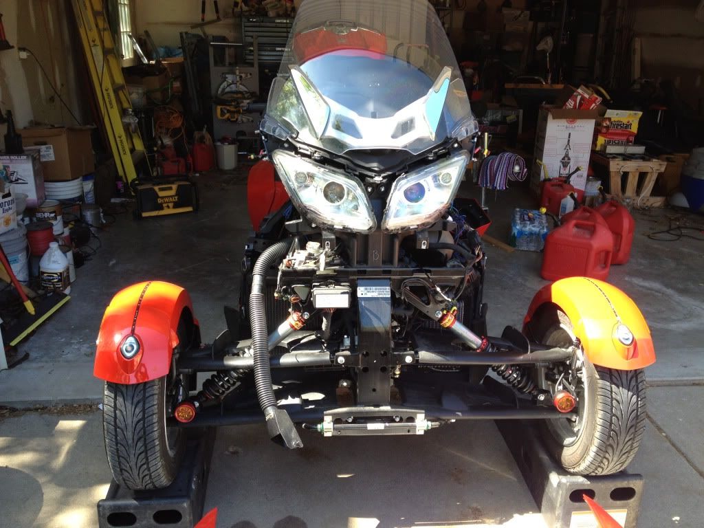
Essentially, there are 4 bolts on top that hold it in place, 4 bolts on the underside that go up through the colored part of the lower spoiler and skid plate, and 2 bolts that go from the frame to the frunk. I don't have a pic of that last one, but if you lay under the bike while on ramps you'll see where the 2 bolt heads thread in from the metal side into a nylon nut on the frunk. Once you remove these 10 bolts (18 if you have SpyderPops Bump Skid, it will have to come off and 4 of those are the original 4 that went through the spoiler and skid plate) There are several harness connections that will have to be separated before removing the frunk. Once you think that you have them all (don't forget that the cable that attaches to the trunk release also has to be separated) Lift the front of the frunk by grabbing it under the fog lights to roughly 15° or so. It is on a hinge type lip. Lift up and out wiggling back and forth a bit for the large frunk panel to clear and then set it down on the box or whatever you made from measuring the height. You'll find that there are probably going to be 2 harnesses that you missed, one on each side. Unplug once all is disconnected and take pics for putting them back in the right place. The frunk is not that heavy, but it is a little awkward and if you don't have the best of backs get a helper or two.
Now that it's off, make sure that you do whatever it is that you have to and make sure that it's right. I placed my remote unit in, soldered a pig tail for my LED under carriage, routed it down through the firewall area and gave myself about 2' extra of 4 channel wire that I zip tied and placed where I can reach it when I get to the lights. I can't stress the 'taking of pics' as you undress this thing. In order to get the frunk off you have to take off most of the panels. I'm putting Lamont's link for RT panel removal video at the end of this paragraph. It's very straight forward and worth the watch. I would add this to the video though. It's still cold in most areas. The mirrors are gonna have to come off. If you do it while it's cold you run the risk of breaking the 2 clips that hold each mirror on. I suggest that you throw some large soft towels in the dryer and get them good and hot. fold them over a few times (longwise) and drape it over each mirror. Leave it for 5 minutes and when you come back it should be ready to pop off. It's easier than a hair dryer.
http://www.spyderlovers.com/forums/...nels-off-and-on-video&highlight=panel+removal
I will try to post some good pics later on. I'll have to run them through Photoshop to put in the arrows and circles and what not. Wife wants to go out for dinner so we're suiting up and taking the Spyder out for dinner. Ciao!
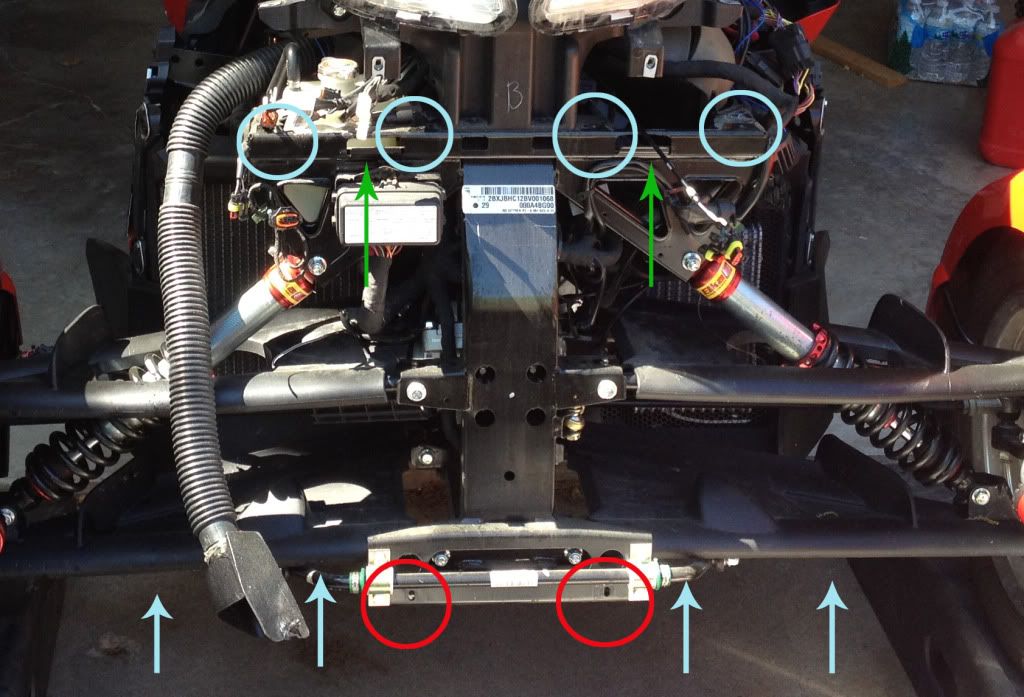
OK, here is a reference photo that I am going to blow up in PS and try to point out the areas that you need to know about.
BTW, the shop vac hose looking thingy is my Ram Air Induction. Installed by Len's guys at Cowtown. It fits into the top left inlet if you're looking at it from the front.
What's what:
Light Blue Circles - Where the 4 top bolts are that connect the frunk. Where plastic meets metal is where the frunk stops. Keep that in mind as you look at it.
Red Circles - The 2 bottom bolts that insert from the back forward. Where you see the holes will actually pass through a nylon nut that in the frunk's mount.
Blue Arrows (up) - This is roughly where you'll find the 4 bolts underneath when you go to take out your skid plate bolts.
Green Arrows - This is the hinged lip that the frunk sets in. I guess you could call this the male part and the receiving part on the frunk would be female. When you pivot the frunk up, this is where the pivot point will be. Then lift up and forward a few inches and set it back down on the box that you WILL have ready. Then you will be able to make sure that you have released all connections and trunk release cable ( just like a bike's brake cable). Once that is done you can simple lift or roll the frunk away to do whatever farkling you have in mind.
Back to where I put my farkling farkles. This is the receiver/power supply for my LED unit.
As you look at the bike from the front, the right side has room to put in a FuzeBlock and or a LED remote. The remote receiver is the black box that has the writing
upside down. The RGB and W wires are out going lines to the RGB strips. The armored cable is what houses the 2 wire harness made of black and red 12g stranded
wire and 3/8" automotive plastic housing (available at all automotive stores).
NOTE: There are bolts in between the top 4 that have nothing to do with the frunk. Remember, plastic to metal only, will be undone. The top 4 bolts screw into J nuts or push nuts. The bottom 2 go through the metal frame and screw into Nylon nuts in the frunk's receiving part. The frunk will not fall off when you undo all the bolts. Only after you tilt the nose, raise it up, pull it forward a few inches and set it on the cradle the you made or improvised, will it come free.
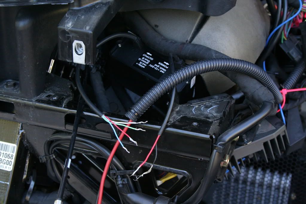
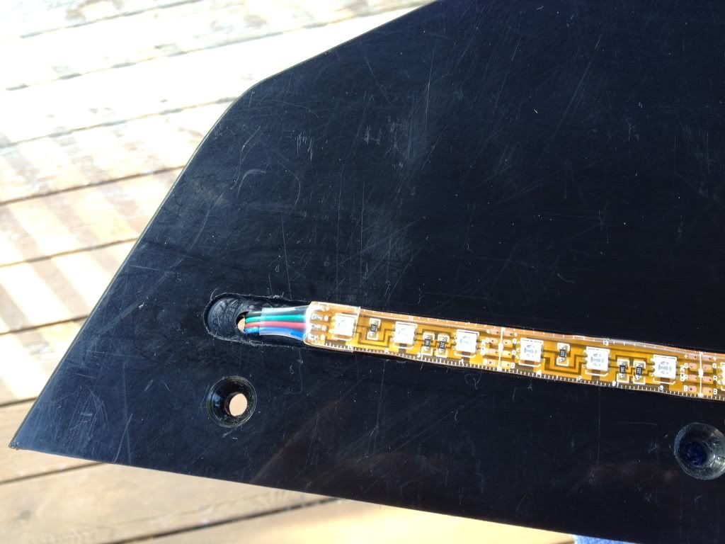
I have also added a pig tail that I can plug all of my wires into after the frunk is back on. I have not cut, soldered or placed the LED under lighting yet. Still to come: SpyderPops Skid Bump has to have a routed channel that's 1/2" wide by about an 1/8" deep. That will protect it from being pulled out by the first stray Armadillo that we encounter that doesn't make it across the road in time.
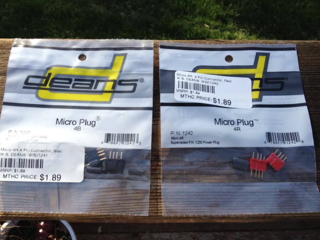
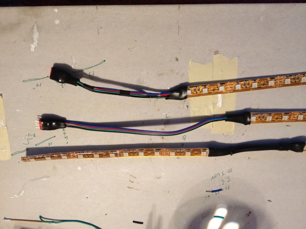
I have measured and marked off where I'm going to router the 1/2" channels on my Bump Skid using masking tape. I'll clamp a steel straight edge in the proper place for a clean, true cut. Since I'm using RGB LED's I'll be using 4 wire and therefore will need a 4 pin connector to solder to the pigtail that I installed while the frunk was off. That way I can pull the frunk without having to cut the wires. Just unplug them. So, what did I use? Talked with Phil about this and he told me what he used, but I opted for something a little different. RC planes, Helis and 4WD buggies are another one of my hobbies. Futaba and JR radio control manufacturers use 3 pin connectors for servos and 4 pin for battery/receiver and other functions. Below is a pic of Dean's Micro Connectors (4 pin). Don't forget that your local hobby shops have some great stuff that you can't get at Auto Zone, Pep Boys or O'Reilly's. Especially if you are looking for small electrical switches, plugs etc. These were only $ 1.89 for a male/female plug set. You can get them in black or red in the event that you have more than one connection and don't want to get confused. See below:
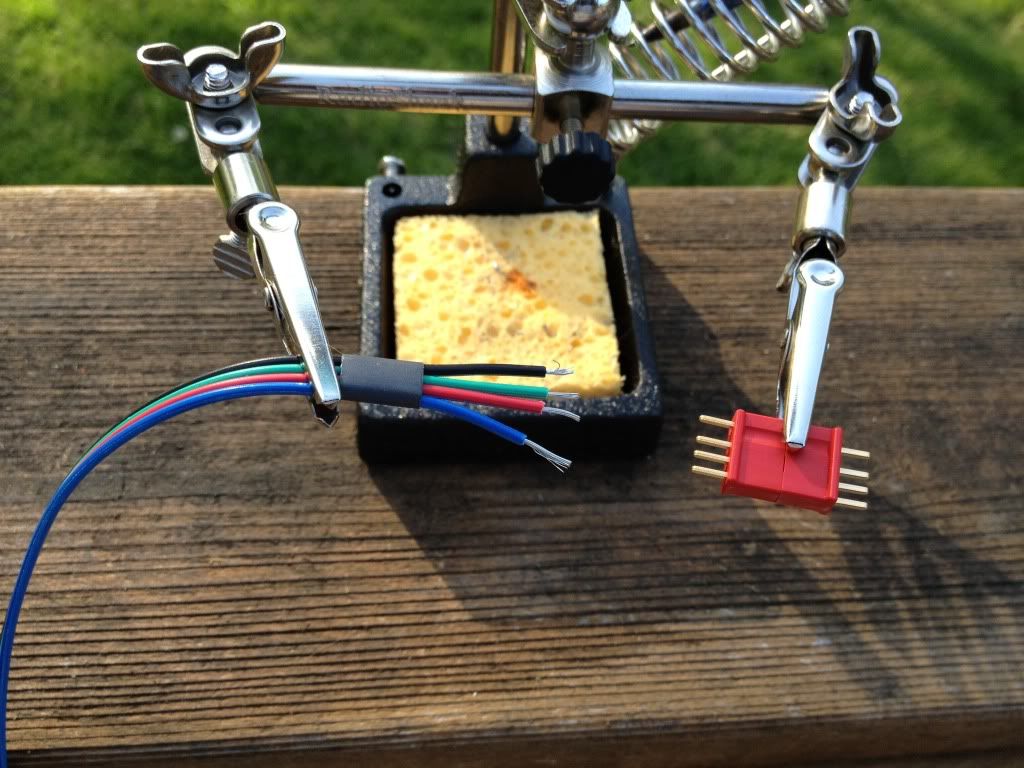
For a better shot on how these look prior to soldering your connections. Don't forget to put your heat shrink tubing on before soldering. It's easy to forget that step.
Next Steps: will be a few soldered extensions using Dean's Micro Clips and the channels to be routed out on the Bump Skid and light testing.
I've run a plunge router through the three areas that I wanted to add my custom lighing to.
Below:
I have routed three channels just deep enough to protect the 3M stickum. I didn't want to jeopardize the strength of the Bump Skid by making the channels deep enough to hide the entire strip. These are thick LED weather proof, silicon rolls. I peeled the tape off of the longest RGB run and placed it. This pic will show that one is installed and the other two are setting astride of their routed channels.
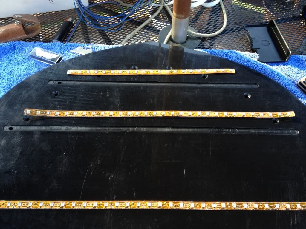
This is a pic of the one LED strip that's soldered and run through. I will silicon both ends to seal.
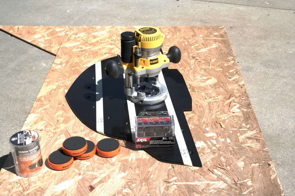
If you decide that you want to add LED underlighting, have a Bump Skid and want to recess your strips by routing, holding it in place and using a straight edge is a must. Your lines don't have to be perfectly straight, but they can't be zig zaggy. A 1/2" channel bit will be perfect for most LED strips. In this photo you'll see that I used a product called 'Bench Cookies'. They are hockey puck shapes with soft rubber on top and bottom. Bench Cookies are about $10 at Lowe's. I placed them under my skid plate and it held fast even during the vibration and movement from the router. I clamped a steel edge in place where the router guide and the bit would cut exactly where I wanted it.
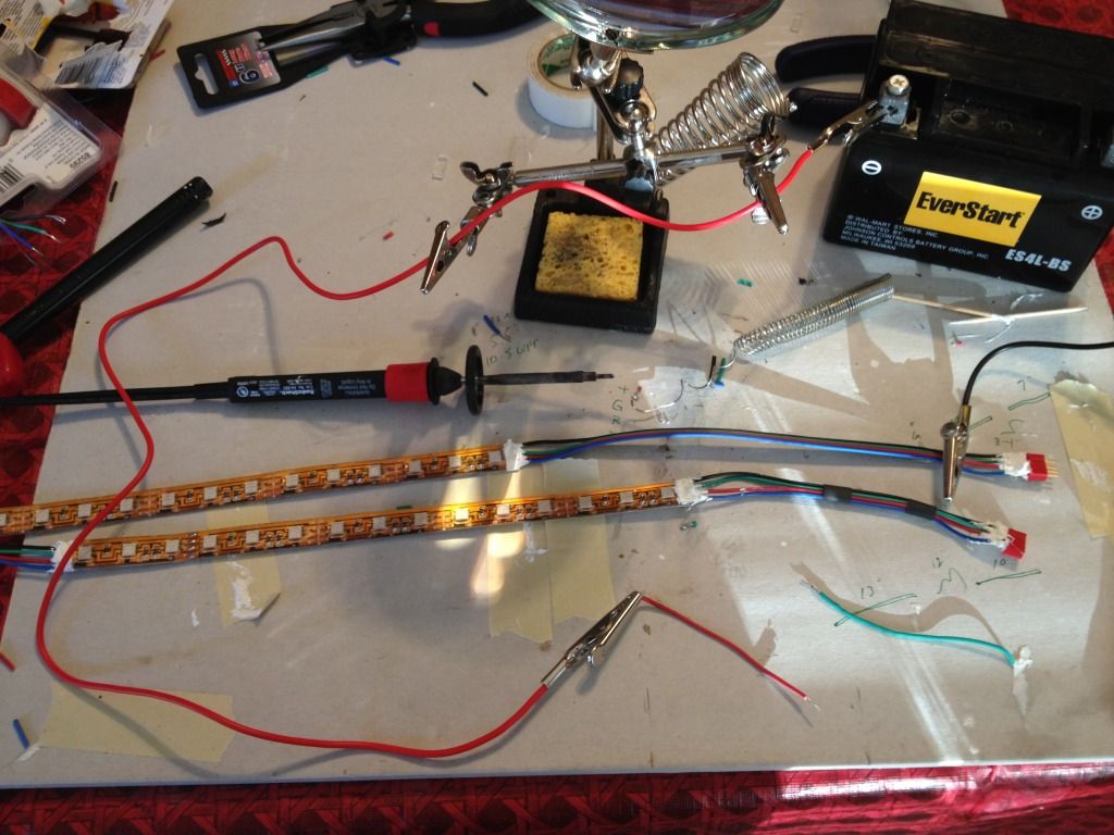
Today, I cut several pieces of LED's and did a lot of soldering. I'm trying to measure the areas under the bike where I want them and then custom cut, wire, solder and heat shrink them prior to attaching. My soldering skills are not very good. Some of my joints are very close to each other. Since I'm using RGB LED's a short isn't a problem that will keep them from lighting. What will happen, for instance, is if my RED lead and the GREEN lead touch/short, it won't blow, but it will make YELLOW. Since, my program uses RGB it will make all of the rest of my colors GREEN while the shorted strip will be YELLOW. So, in order to keep these connections from doing that I took an extra step of using tubed Silicon to coat the soldered joints. That way, when I got to heat shrink the tubing the Silicon between the soldered joint won't be able to touch. Once dry, I'll use a heat gun or light torch to seal them. My connections are butt ugly, especially with all the white silicon pasted around them, but once the black heat shrink is on it... it's a piece of art and it still lights!
This shows where I dotted the soldered connections with Silicon. It's not pretty, but once the heat shrink tubing is on, you can't see it. I'm hoping that this will lengthen the longevity of this lighting project. I really don't want to do this again.
It looks better after the tubing has been shrunk
Hopefully, my next posts will show these lit up.
I got all three LED strips in, wired, silconed, heat shrunk and liquid elctrical taped. The pig tail for the Bump Skid is soldered with the mating plug that goes to the extension that I ran from the remote/power supply. I took pics with my iPhone, but they turned out poorly. I'll run them through a clarity program to see if it's worth posting or not. The long and the short of it is that I now have a brightly lit, under frunk lighting in all the colors of the rainbow. Pretty cool. I'll post all relevent pics and posts soon. Long work days and getting Spyderfest events ready is taking away some precious limited time that I have to get my bike ready for Friday Night Lights.
In a non - LED related note: I now have Lamont's HWY brackets and pegs on my bike. SWEET! We had to put a twist in them to make them more comfy for me. I still have some minor adjustments to make to fit my leg length better, but that's to be expected of any foot rests. Nice job on the peg design, Lamont!
NEW: Posted 5/8/2012
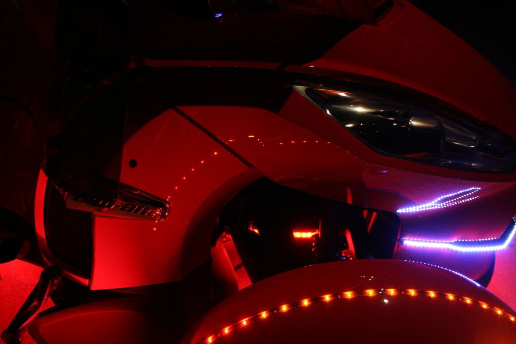
The following pics are the end result. LED's are at best, a real bear to photograph and turn out decent. I tried HDR shooting, but that doesn't work well in low light levels. I won't show all the colors that the under lighting does, but being RGB they can replicate all of the colors of the spectrum, including white. Your choice of remote systems is what will limit you. Since I have my bike up on the lift periodically, I couldn't put the strips directly under the main frame for obvious reasons. Instead, I installed them on the sides of the frame. As much fun and learning experience that this was, I'm not sure that going this route was the most economical or the best looking. The LED RGB strips are awesome from SuperbrightLEDs.com, but their remotes pretty much suck eggs. I'll have to pull the frunk to replace the receiver that's in there, but it'll be worth it. I'm going to keep my existing setup, but I'm going to get the rest of my lights from Reggy at TricLED.com.
He'll get you anything that you need and he has some really killer stuff. That's where my next remote system is coming from. I'm not trying to discourage anyone from trying this, but if your soldering skills aren't the best, this will be an exhausting task. If you decide to really decorate your panels you'll have to consider disconnect options. If you're only dealing with one color strips, TricLED has some great quick disconnects that will allow you or your technician to remove panels without having to cut your wires or worse, pull them out of a soldered joint on accident.
Here you're looking through the shock. You can see the red strip running along the side of the main frame. This is where it's kind of cool to do it this way. The light throws out sideways and lights up the mechanics of the shocks, steering arms and inside wheel.
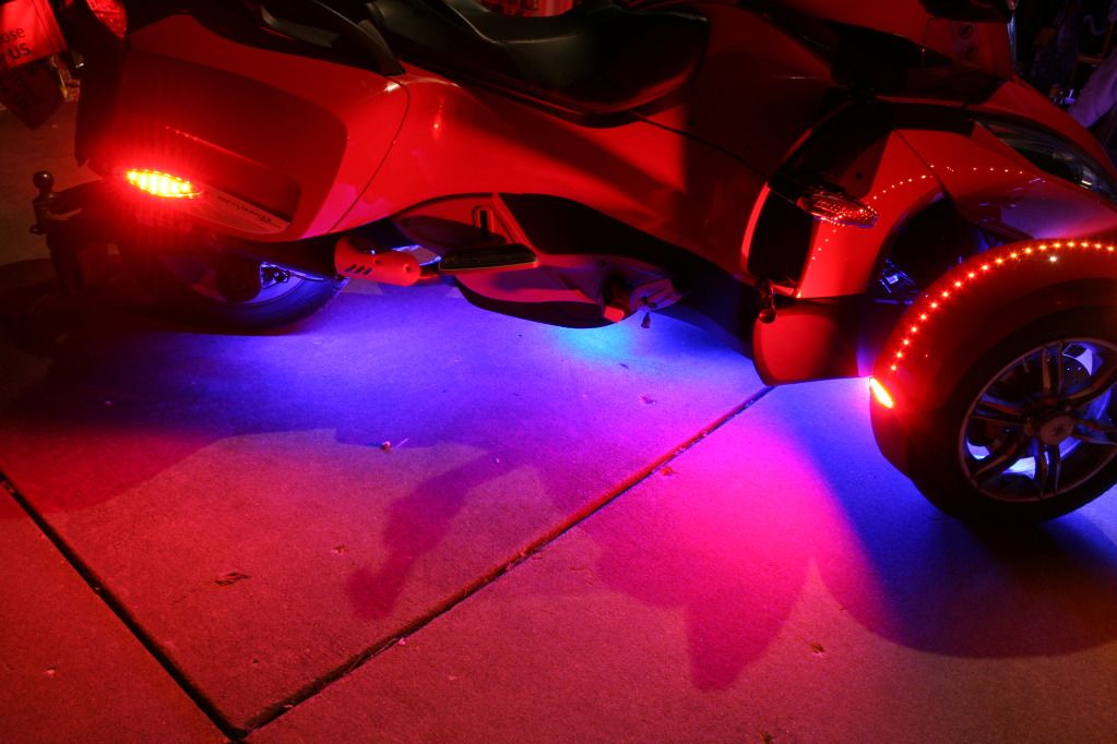
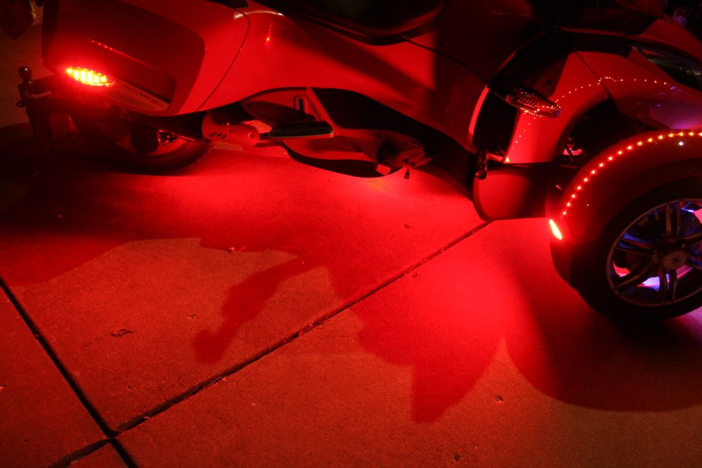
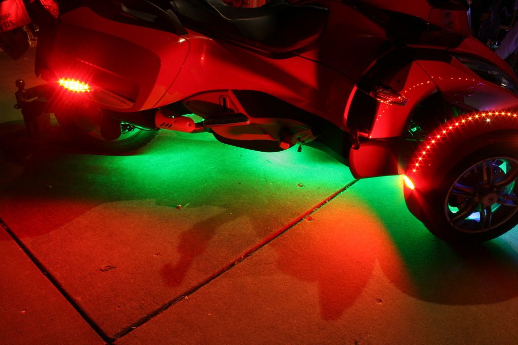
Some of the color shots:
Aqua -
Yellow -
Blue -
Really really Red -
Green -
If you have any questions feel free to msg or email me. I hope to really have this baby looking tops for SpyderFest 2013. Hope to see you there!
Here is a shot of where I can get to the fuse for replacement or trouble shooting.
I left hot pink Zip Ties in place so that you could see where the new power lines were routed to the frunk. After getting into it, I realized that I wasn't comfy putting the FuzeBlock and the LED receiver in the same area, so I opted to just place the LED unit in. It's pretty large and there was enough room to place it securely.
I'll do my best to describe how to pull the frunk. I used car ramps to pull the bike up on. Since ramps vary in height and shocks sit differently, you'll have to pull your bike up and then measure the distance from the lowest point from the frunk and the ground. The reason for this is that it's much easier to hook up the wire connections when it's sitting at close to it's original position when putting the frunk on and off. I got lucky and happened to have a Hoover Vacuum box that was just at the right height.
Essentially, there are 4 bolts on top that hold it in place, 4 bolts on the underside that go up through the colored part of the lower spoiler and skid plate, and 2 bolts that go from the frame to the frunk. I don't have a pic of that last one, but if you lay under the bike while on ramps you'll see where the 2 bolt heads thread in from the metal side into a nylon nut on the frunk. Once you remove these 10 bolts (18 if you have SpyderPops Bump Skid, it will have to come off and 4 of those are the original 4 that went through the spoiler and skid plate) There are several harness connections that will have to be separated before removing the frunk. Once you think that you have them all (don't forget that the cable that attaches to the trunk release also has to be separated) Lift the front of the frunk by grabbing it under the fog lights to roughly 15° or so. It is on a hinge type lip. Lift up and out wiggling back and forth a bit for the large frunk panel to clear and then set it down on the box or whatever you made from measuring the height. You'll find that there are probably going to be 2 harnesses that you missed, one on each side. Unplug once all is disconnected and take pics for putting them back in the right place. The frunk is not that heavy, but it is a little awkward and if you don't have the best of backs get a helper or two.
Now that it's off, make sure that you do whatever it is that you have to and make sure that it's right. I placed my remote unit in, soldered a pig tail for my LED under carriage, routed it down through the firewall area and gave myself about 2' extra of 4 channel wire that I zip tied and placed where I can reach it when I get to the lights. I can't stress the 'taking of pics' as you undress this thing. In order to get the frunk off you have to take off most of the panels. I'm putting Lamont's link for RT panel removal video at the end of this paragraph. It's very straight forward and worth the watch. I would add this to the video though. It's still cold in most areas. The mirrors are gonna have to come off. If you do it while it's cold you run the risk of breaking the 2 clips that hold each mirror on. I suggest that you throw some large soft towels in the dryer and get them good and hot. fold them over a few times (longwise) and drape it over each mirror. Leave it for 5 minutes and when you come back it should be ready to pop off. It's easier than a hair dryer.
http://www.spyderlovers.com/forums/...nels-off-and-on-video&highlight=panel+removal
I will try to post some good pics later on. I'll have to run them through Photoshop to put in the arrows and circles and what not. Wife wants to go out for dinner so we're suiting up and taking the Spyder out for dinner. Ciao!
OK, here is a reference photo that I am going to blow up in PS and try to point out the areas that you need to know about.
BTW, the shop vac hose looking thingy is my Ram Air Induction. Installed by Len's guys at Cowtown. It fits into the top left inlet if you're looking at it from the front.
What's what:
Light Blue Circles - Where the 4 top bolts are that connect the frunk. Where plastic meets metal is where the frunk stops. Keep that in mind as you look at it.
Red Circles - The 2 bottom bolts that insert from the back forward. Where you see the holes will actually pass through a nylon nut that in the frunk's mount.
Blue Arrows (up) - This is roughly where you'll find the 4 bolts underneath when you go to take out your skid plate bolts.
Green Arrows - This is the hinged lip that the frunk sets in. I guess you could call this the male part and the receiving part on the frunk would be female. When you pivot the frunk up, this is where the pivot point will be. Then lift up and forward a few inches and set it back down on the box that you WILL have ready. Then you will be able to make sure that you have released all connections and trunk release cable ( just like a bike's brake cable). Once that is done you can simple lift or roll the frunk away to do whatever farkling you have in mind.
Back to where I put my farkling farkles. This is the receiver/power supply for my LED unit.
As you look at the bike from the front, the right side has room to put in a FuzeBlock and or a LED remote. The remote receiver is the black box that has the writing
upside down. The RGB and W wires are out going lines to the RGB strips. The armored cable is what houses the 2 wire harness made of black and red 12g stranded
wire and 3/8" automotive plastic housing (available at all automotive stores).
NOTE: There are bolts in between the top 4 that have nothing to do with the frunk. Remember, plastic to metal only, will be undone. The top 4 bolts screw into J nuts or push nuts. The bottom 2 go through the metal frame and screw into Nylon nuts in the frunk's receiving part. The frunk will not fall off when you undo all the bolts. Only after you tilt the nose, raise it up, pull it forward a few inches and set it on the cradle the you made or improvised, will it come free.
I have also added a pig tail that I can plug all of my wires into after the frunk is back on. I have not cut, soldered or placed the LED under lighting yet. Still to come: SpyderPops Skid Bump has to have a routed channel that's 1/2" wide by about an 1/8" deep. That will protect it from being pulled out by the first stray Armadillo that we encounter that doesn't make it across the road in time.
I have measured and marked off where I'm going to router the 1/2" channels on my Bump Skid using masking tape. I'll clamp a steel straight edge in the proper place for a clean, true cut. Since I'm using RGB LED's I'll be using 4 wire and therefore will need a 4 pin connector to solder to the pigtail that I installed while the frunk was off. That way I can pull the frunk without having to cut the wires. Just unplug them. So, what did I use? Talked with Phil about this and he told me what he used, but I opted for something a little different. RC planes, Helis and 4WD buggies are another one of my hobbies. Futaba and JR radio control manufacturers use 3 pin connectors for servos and 4 pin for battery/receiver and other functions. Below is a pic of Dean's Micro Connectors (4 pin). Don't forget that your local hobby shops have some great stuff that you can't get at Auto Zone, Pep Boys or O'Reilly's. Especially if you are looking for small electrical switches, plugs etc. These were only $ 1.89 for a male/female plug set. You can get them in black or red in the event that you have more than one connection and don't want to get confused. See below:
For a better shot on how these look prior to soldering your connections. Don't forget to put your heat shrink tubing on before soldering. It's easy to forget that step.
Next Steps: will be a few soldered extensions using Dean's Micro Clips and the channels to be routed out on the Bump Skid and light testing.
I've run a plunge router through the three areas that I wanted to add my custom lighing to.
Below:
I have routed three channels just deep enough to protect the 3M stickum. I didn't want to jeopardize the strength of the Bump Skid by making the channels deep enough to hide the entire strip. These are thick LED weather proof, silicon rolls. I peeled the tape off of the longest RGB run and placed it. This pic will show that one is installed and the other two are setting astride of their routed channels.
This is a pic of the one LED strip that's soldered and run through. I will silicon both ends to seal.
If you decide that you want to add LED underlighting, have a Bump Skid and want to recess your strips by routing, holding it in place and using a straight edge is a must. Your lines don't have to be perfectly straight, but they can't be zig zaggy. A 1/2" channel bit will be perfect for most LED strips. In this photo you'll see that I used a product called 'Bench Cookies'. They are hockey puck shapes with soft rubber on top and bottom. Bench Cookies are about $10 at Lowe's. I placed them under my skid plate and it held fast even during the vibration and movement from the router. I clamped a steel edge in place where the router guide and the bit would cut exactly where I wanted it.
Today, I cut several pieces of LED's and did a lot of soldering. I'm trying to measure the areas under the bike where I want them and then custom cut, wire, solder and heat shrink them prior to attaching. My soldering skills are not very good. Some of my joints are very close to each other. Since I'm using RGB LED's a short isn't a problem that will keep them from lighting. What will happen, for instance, is if my RED lead and the GREEN lead touch/short, it won't blow, but it will make YELLOW. Since, my program uses RGB it will make all of the rest of my colors GREEN while the shorted strip will be YELLOW. So, in order to keep these connections from doing that I took an extra step of using tubed Silicon to coat the soldered joints. That way, when I got to heat shrink the tubing the Silicon between the soldered joint won't be able to touch. Once dry, I'll use a heat gun or light torch to seal them. My connections are butt ugly, especially with all the white silicon pasted around them, but once the black heat shrink is on it... it's a piece of art and it still lights!
This shows where I dotted the soldered connections with Silicon. It's not pretty, but once the heat shrink tubing is on, you can't see it. I'm hoping that this will lengthen the longevity of this lighting project. I really don't want to do this again.
It looks better after the tubing has been shrunk
Hopefully, my next posts will show these lit up.
I got all three LED strips in, wired, silconed, heat shrunk and liquid elctrical taped. The pig tail for the Bump Skid is soldered with the mating plug that goes to the extension that I ran from the remote/power supply. I took pics with my iPhone, but they turned out poorly. I'll run them through a clarity program to see if it's worth posting or not. The long and the short of it is that I now have a brightly lit, under frunk lighting in all the colors of the rainbow. Pretty cool. I'll post all relevent pics and posts soon. Long work days and getting Spyderfest events ready is taking away some precious limited time that I have to get my bike ready for Friday Night Lights.
In a non - LED related note: I now have Lamont's HWY brackets and pegs on my bike. SWEET! We had to put a twist in them to make them more comfy for me. I still have some minor adjustments to make to fit my leg length better, but that's to be expected of any foot rests. Nice job on the peg design, Lamont!
NEW: Posted 5/8/2012
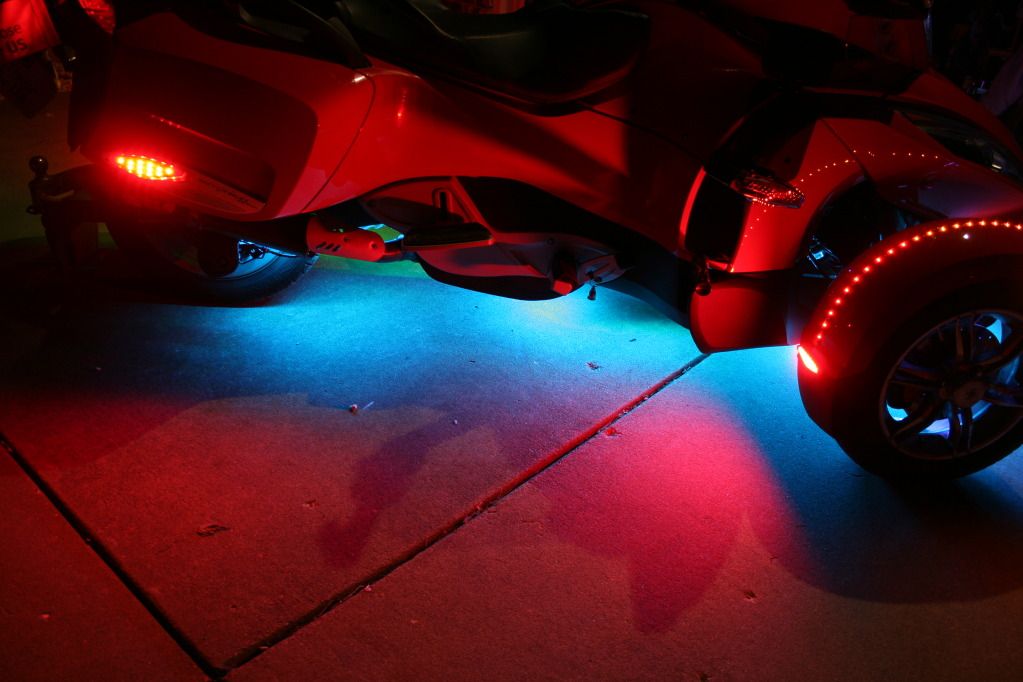
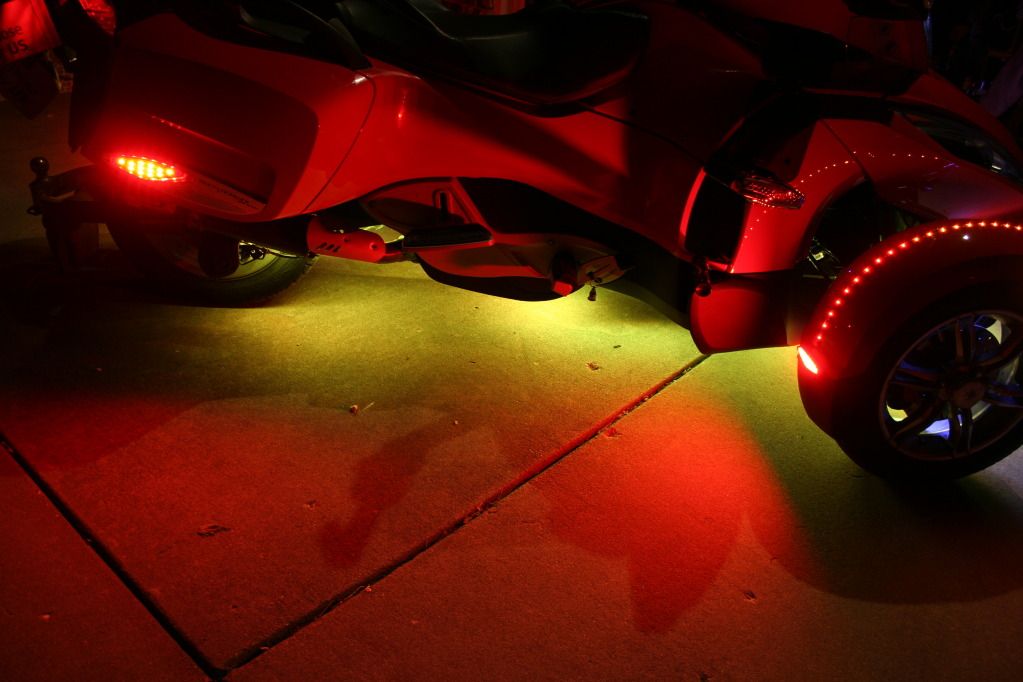
The following pics are the end result. LED's are at best, a real bear to photograph and turn out decent. I tried HDR shooting, but that doesn't work well in low light levels. I won't show all the colors that the under lighting does, but being RGB they can replicate all of the colors of the spectrum, including white. Your choice of remote systems is what will limit you. Since I have my bike up on the lift periodically, I couldn't put the strips directly under the main frame for obvious reasons. Instead, I installed them on the sides of the frame. As much fun and learning experience that this was, I'm not sure that going this route was the most economical or the best looking. The LED RGB strips are awesome from SuperbrightLEDs.com, but their remotes pretty much suck eggs. I'll have to pull the frunk to replace the receiver that's in there, but it'll be worth it. I'm going to keep my existing setup, but I'm going to get the rest of my lights from Reggy at TricLED.com.
He'll get you anything that you need and he has some really killer stuff. That's where my next remote system is coming from. I'm not trying to discourage anyone from trying this, but if your soldering skills aren't the best, this will be an exhausting task. If you decide to really decorate your panels you'll have to consider disconnect options. If you're only dealing with one color strips, TricLED has some great quick disconnects that will allow you or your technician to remove panels without having to cut your wires or worse, pull them out of a soldered joint on accident.
Here you're looking through the shock. You can see the red strip running along the side of the main frame. This is where it's kind of cool to do it this way. The light throws out sideways and lights up the mechanics of the shocks, steering arms and inside wheel.
Some of the color shots:
Aqua -
Yellow -
Blue -
Really really Red -
Green -
If you have any questions feel free to msg or email me. I hope to really have this baby looking tops for SpyderFest 2013. Hope to see you there!
Last edited:

")
 pps
pps ray:
ray:
")