What's the best way to get power to my Zumo 396 on my 2020 Spyder RTL? Do I run the red and black wires of the GPS to the pos and neg posts on the battery? I'm obviously not a mechanic, any help would be appreciated. Thanks,
Steve
Steve, I hope you haven't given up hope but performing the electrical connection and then documenting it (after I was certain everything worked properly) took more time than I expected. Most things I do end up being that way, but thus far my efforts have been successful. So . . . here's what I did and here are pictures I hope will make the steps understandable. But before the wiring steps I should say I've mounted the 396 using one of Lamonster's GPS mounts and it is an excellent choice, in my opinion. Anyway, here goes:
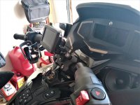
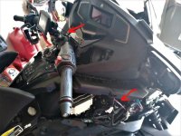
First, remove the right speaker grill. Lift from the inside edge (red arrow). I fed the end of the cable that plugs into the Garmin mount up through the speaker opening and through the large metal wire guide and finally through upper opening at the handle bar center. I then install the power plug into the Garmin mount (take care not to lose the tiny black screw that secures the power plug to the GPS mounting bracket). The black inline box makes it impossible to feed the cable any other way as near as I can determine.
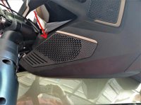
Next, remove the upper right side panel. Pull the tab at the rear of the panel (red pointer) and gently tug. The clips will release one after the other.
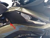
Next remove the lower side panel by pulling at the rear edge, or along the rear portion of the top, gently releasing the clips and then pulling slightly rearward to release the two locating tabs on the front edge of the panel.
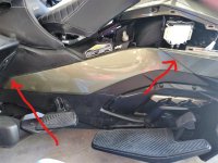
Next remove the large lower panel that is held in place by three Torx screws . . .
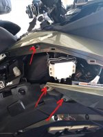
. . . And three push pins that can be accessed by opening the front trunk.
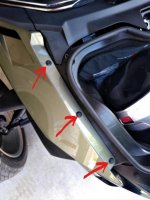
Note: there are two locating tabs beneath the bottom edge of the panel near the shock that have to be released. Finally slide the panel toward the front of the Spyder to release the locating tabs inside the air scoop.
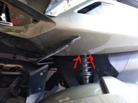
This is the view after the three panels are removed. The important thing is that you now have access to the OEM accessory power cable and connector (note the blue butt connectors). The task is to tap into that cable to have switchable power for the GPS.
IMPORTANT NOTE: Several forum sponsor merchants have mentioned there may be a polarity issue with the accessory power cable on 2020 RT models. It can be tested with a multimeter or, as I tested our 2021. After stripping wires (refer to the next step below) I simply twisted the exposed GPS and accessory ground wires together (black), turned on the ignition, and touched the power wires together. The GPS activated.
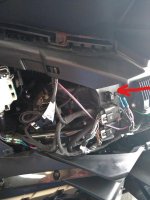
To splice the GPS wires into the accessory power cable I unplugged the cable and removed a section of the cloth wrapping to gain access to the two individual wires. I left about 1 1/2 inches on the connector (plug) end of the OEM cable, and cut each wire. I then stripped about 1/4 inch of insulation from each of the four wire ends. I then crimped a butt connector onto each of the plug-end wires. I then twisted the GPS power and ground wires to the accessory power cable power and ground wires and crimped each into the appropriate butt connector. Finally, I plugged the accessory power cable into its receptacle and switched on the ignition to determine if the GPS would come to life. It did, and when I switched the ignition off, after the Spyder concluded its shut down process, the GPS turned off. This is what the finished product looks like.
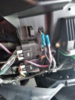
Here is the finished product before replacing the panels. You can see the black GPS wire disappearing into the steering hub and the red GPS wire on its way to the accessory power outlet. The excess cable and GPS black box are coiled in the space below the speaker and wire tied to a convenient cable. The red wire is wire tied several times just to keep things tidy.
All that remains is to re-install the three panels - in the reverse order from witch they were removed. When installing the third (large) panel, start by aligning the locating tabs in the air scoop first, then the two locating tabs at the bottom of the panel, then the remaining tabs. Finally, install the three Torx screws and three push pins.
Align the two locating tabs at the front of the second panel and then tap the remaining clips into place. The third panel simply snaps into place after aligning the clips with their respective receptacles.
This may seem daunting but it really isn't. It took longer to sort out the pictures and write the text than it took to do the job. I'm not a highly skilled tinkerer but I've managed four alterations to my wife's Sea to Sky thus far and have succeeded in each effort. The alterations: Spyder Pops LED mirror-mount running/turn signal lights, Show Chrome adjustable/removable rider's back rest, KOTT stainless grill guards, and the GPS power task.
I hope this may help your wiring effort. And if you have any questions please don't hesitate to ask.


