-
There were many reasons for the change of the site software, the biggest was security. The age of the old software also meant no server updates for certain programs. There are many benefits to the new software, one of the biggest is the mobile functionality. Ill fix up some stuff in the coming days, we'll also try to get some of the old addons back or the data imported back into the site like the garage. To create a thread or to reply with a post is basically the same as it was in the prior software. The default style of the site is light colored, but i temporarily added a darker colored style, to change you can find a link at the bottom of the site.
You are using an out of date browser. It may not display this or other websites correctly.
You should upgrade or use an alternative browser.
You should upgrade or use an alternative browser.
Phil's 2014 (neww) DARTH Mods
- Thread starter Phil
- Start date
SPECTACUALR SPIDERMAN
Active member
take me to your leader
NoLmtz
New member
Phil, I'm just down the road from you (relatively in Texas miles)!! I only want to do a fraction of what you've done... you should host a bootcamp for Spyder accessorizing!! :firstplace:
Your additions are incredible... keep them coming! :bowdown::bowdown:
Love the projections, will be checking those out in more detail!!
Your additions are incredible... keep them coming! :bowdown::bowdown:
Love the projections, will be checking those out in more detail!!
mtdoragary
New member
How much, if any, brightness did you lose by putting he reflectors over the LED's?
finless
New member
Phil check this out
Hey Phil, another guy posted where BRP gets thier switches.
I bet this would fit inbetwen the 4 others on the RT. Use it to turn on your light systesm")
http://www.otrattw.net/CONTURA-V-ALIEN-LIGHTS-LOWER-LED-INDEPENDENT-V1D1JHHB-PZCAL-100.html
Bob
Hey Phil, another guy posted where BRP gets thier switches.
I bet this would fit inbetwen the 4 others on the RT. Use it to turn on your light systesm
http://www.otrattw.net/CONTURA-V-ALIEN-LIGHTS-LOWER-LED-INDEPENDENT-V1D1JHHB-PZCAL-100.html
Bob
Phil
Mod Monster
How much, if any, brightness did you lose by putting he reflectors over the LED's?
I lost a LITTLE. BUT... in my mind the Brightsides are SO bright, they would do well to go down a little bit. I actually wanted to add another diffuser material between the light and the reflector (which also would slightly lower the brightness), but the material doesn't want to hold glue that well.
Phil
Mod Monster
Hey Phil, another guy posted where BRP gets thier switches.
I bet this would fit inbetwen the 4 others on the RT. Use it to turn on your light systesm
http://www.otrattw.net/CONTURA-V-ALIEN-LIGHTS-LOWER-LED-INDEPENDENT-V1D1JHHB-PZCAL-100.html
Bob
Thanks Bob! Great to know!
I actually have all of the lights come on with the switch. The TOTAL draw for everything is about 7-8 amps, so it's not really any issue. AND, with the remote control I can turn them all on/off and/or dim and/or do the zones separately.

Phil
Mod Monster
Phil, I'm just down the road from you (relatively in Texas miles)!! I only want to do a fraction of what you've done... you should host a bootcamp for Spyder accessorizing!! :firstplace:
Your additions are incredible... keep them coming! :bowdown::bowdown:
Love the projections, will be checking those out in more detail!!
I'd love to put something together here in Tyler for anyone that would come. Maybe get Lamont and Harvey to come and do some laser alignments, have some food, fellowship, and show how we do some of the things we do.
mtdoragary
New member
Love your SpyderIcthus logo!
Phil
Mod Monster
Phil
Mod Monster
I have a friend that is an electrical engineer with a specialty in battery management systems. His patented system is used at cell sites around the world and go so far as to predict which battery or cell will fail and when. It is a phenomenal tool. You can read more here... www.btechinc.com
This is not a BTECH solution") . But this is a similar solution minus a bit of battery science. This guy measures not only voltage (lots of products do that) but it tells you the status of a battery's condition. The forward charging current, the discharge current (like when I run all of the LEDs with the engine off), and time left on the battery in discharge. To do all of this, and leave an electrical system intact, you need one of the things in the middle above the battery- a smart shunt resistor. It is in series with the ground as you can see. The smarts measures the current across the shunt, yet the shunt has ZERO effect on the starting and operation of the bike.
. But this is a similar solution minus a bit of battery science. This guy measures not only voltage (lots of products do that) but it tells you the status of a battery's condition. The forward charging current, the discharge current (like when I run all of the LEDs with the engine off), and time left on the battery in discharge. To do all of this, and leave an electrical system intact, you need one of the things in the middle above the battery- a smart shunt resistor. It is in series with the ground as you can see. The smarts measures the current across the shunt, yet the shunt has ZERO effect on the starting and operation of the bike.
The grey wire connects the shunt to the meter in the dash (pic later). All of it mounts nicely above the battery. The solution is the BMV700 from Victron Energy-- http://www.victronenergy.com/battery-monitors/bmv700/
.

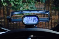
Here's a view of the meter in one of it's 8-10 metering modes-

This is not a BTECH solution
. But this is a similar solution minus a bit of battery science. This guy measures not only voltage (lots of products do that) but it tells you the status of a battery's condition. The forward charging current, the discharge current (like when I run all of the LEDs with the engine off), and time left on the battery in discharge. To do all of this, and leave an electrical system intact, you need one of the things in the middle above the battery- a smart shunt resistor. It is in series with the ground as you can see. The smarts measures the current across the shunt, yet the shunt has ZERO effect on the starting and operation of the bike. The grey wire connects the shunt to the meter in the dash (pic later). All of it mounts nicely above the battery. The solution is the BMV700 from Victron Energy-- http://www.victronenergy.com/battery-monitors/bmv700/
.
Here's a view of the meter in one of it's 8-10 metering modes-
Last edited:
nikki.ullis
New member
:shemademe_smilie: Phil i'm telling my other half on you. My gobo purchase in the next few days is ALL YOUR FAULT! LOL!
I almost got my LEDs installed how I want them, came on the forums to see if you had anymore good ideas.
you never disappoint sir!
I almost got my LEDs installed how I want them, came on the forums to see if you had anymore good ideas.
you never disappoint sir!
Phil
Mod Monster
:shemademe_smilie: Phil i'm telling my other half on you. My gobo purchase in the next few days is ALL YOUR FAULT! LOL!
I almost got my LEDs installed how I want them, came on the forums to see if you had anymore good ideas.
you never disappoint sir!
Happy to be your excuse

MarkLawson
RT-S PE#0031
Phil, I must have found what was wrong because when I looked at the picture, I kept repeating to myself,
"That's just WRONG...That's just WRONG...That's just WRONG..."
Phil
Mod Monster
You are giving me way too much credit Phil.
I don't have a clue and yes I did stare at it for quite a while.
Wiring is an art form best not overthought.
My education is in cypher codes so if you want to break into the Dish Network I'm your guy :roflblack:
If you want your LEDs to light, better find someone who can tell an anode from a cathode.
As long as the red wires are connected so they are carrying positive current and the black wires look like they are negative juicers it looks copacetic to me.
HA!!! We need to hang out more Roger!
The answer is that there are still two negative device wires attached to the battery, bypassing the shunt. In FACT, one of those two is the negative side of the added Fuzeblock that feeds all of the LEDs! So, the shunt would never see the LED load. :banghead:
BYW- I posted on FB, IF YOU ARE THINKING OF PUTTING THIS THING ON A 2014, DO NOT MOUNT IT WHERE I SHOW IT!!! I had measured and looked a lot, but when I was fitting the frunk back in place, it ends up that the shunt sticks out about 1/2" too far. I'm going to move it to one of 3 alternate places that fits best and that is safe (electrically). I've already moved it, and the frunk now fits, but I want to try a couple of things. I'll re-do the pics.
Phil
Mod Monster
Oh Mark.......Phil, I must have found what was wrong because when I looked at the picture, I kept repeating to myself,
"That's just WRONG...That's just WRONG...That's just WRONG..."
Phil
Mod Monster
Oops. I measured and looked, and it didn't fit when fitting the frunk back on. So... Plan B.
Here are the pics and some notes.......
the family shot-

A close up of the shunt in place. It is mechanically stable, but I added industrial Velcro to add stabilization. It is velcro'd to the metal battery clamp. BTW- there is no fear having the bare lugs. This is the negative side of the battery that is at the same potential as the frame. As an installation note, you will need to open up the hole in the lug on the right, in the pic. This is the one that comes with the bike and is connected to the frame. I used a reamer to make it fit the very large bolt that you see on the shunt. Test it often as you ream it out for fit. Reason- the needed hole is JUST a little smaller than the lug!

Closeup of the connection from the battery to the 'input' of the shunt.

Closeup of the 'output' of the shunt. Notice the addition of the braid sheath over the ground. This is for safety only, in case of an accident. It will help keep the positive and the negative wires from coming in contact. On a normal every day use, it will be 100% fine.

Here you can see the meter in place and operating.

This is a view with the frunk back on and the battery access hatch off. You can see the bottom of hte shunt. Once it is all in place and setup, there's really no need to access it. I just wanted you to see where it landed.

Here are the pics and some notes.......
the family shot-
A close up of the shunt in place. It is mechanically stable, but I added industrial Velcro to add stabilization. It is velcro'd to the metal battery clamp. BTW- there is no fear having the bare lugs. This is the negative side of the battery that is at the same potential as the frame. As an installation note, you will need to open up the hole in the lug on the right, in the pic. This is the one that comes with the bike and is connected to the frame. I used a reamer to make it fit the very large bolt that you see on the shunt. Test it often as you ream it out for fit. Reason- the needed hole is JUST a little smaller than the lug!
Closeup of the connection from the battery to the 'input' of the shunt.
Closeup of the 'output' of the shunt. Notice the addition of the braid sheath over the ground. This is for safety only, in case of an accident. It will help keep the positive and the negative wires from coming in contact. On a normal every day use, it will be 100% fine.
Here you can see the meter in place and operating.
This is a view with the frunk back on and the battery access hatch off. You can see the bottom of hte shunt. Once it is all in place and setup, there's really no need to access it. I just wanted you to see where it landed.
Last edited:
gromitdaddy
New member
Phil
Mod Monster

The pic above is the device... I had to do some mod to it to mount it with the RAM system. It's ok, but now that I have the spectacular meter that does SO much, I wanted a different solution. This one is on the way.....Hi,
If I may ask what is this on top of your dash? Been looking through the posts, but see nothing.

Similar threads
- Replies
- 2
- Views
- 427
- Replies
- 9
- Views
- 1K
- Replies
- 2
- Views
- 295