• There were many reasons for the change of the site software, the biggest was security. The age of the old software also meant no server updates for certain programs. There are many benefits to the new software, one of the biggest is the mobile functionality. Ill fix up some stuff in the coming days, we'll also try to get some of the old addons back or the data imported back into the site like the garage. To create a thread or to reply with a post is basically the same as it was in the prior software. The default style of the site is light colored, but i temporarily added a darker colored style, to change you can find a link at the bottom of the site.

New Fuse Panel Location

bluestratos

New member
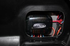
I have a lot of electrical powered accessories and it was becoming a mess. While everything had a fuse, it was difficult to take off modules which caused concern for my dealer. I decided to redo everything starting with a new fuse panel and install weather proof conectors at all logical points to allow for easy module removal.

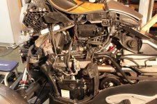
There is plenty of room behind the Frunk as you can see. The fuse panel holds 14 fuses, 7 hot all the time, 7 fed by the acc relay (the trigger wire has a diode in it to prevent feed back). The new harnesses I made are fabric taped to match the stock look for the most part, a few are using split loom. I have more pictures but was having trouble with the resizing software so I will try to edit again from home to add a few more.

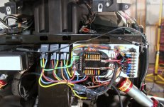
The project took about 16 hours including designing and building the panel arrangement. You can see an example of one of the new connectors hanging just below the fuse panel. I added 8 plugs ranging from a blocks of 6 down to 1. The plugs are made by Delphi, the fuse panel is made by Tsnami. While this was not a cheap upgrade (around $300 with wire) it brings great peace of mind to know the wiring is logically laid out and safe and most of all, my mechanic can work on the the bike and not have to cut any wires.

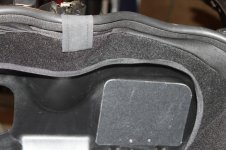
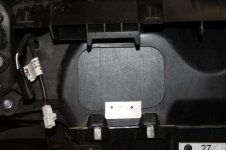
I added a couple more pictures, one of the side of the bike showing a stock looking setup and the back of the frunk showing the access panel.
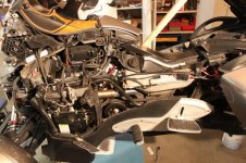
 

Attachments

  • php3To5SQPM.jpg
    php3To5SQPM.jpg
    94 KB · Views: 369
  • phpjpdiz8PM.jpg
    phpjpdiz8PM.jpg
    56.2 KB · Views: 316
  • IMG_5374_Resized.jpg
    IMG_5374_Resized.jpg
    44.5 KB · Views: 234
  • IMG_5370_Resized.jpg
    IMG_5370_Resized.jpg
    84.4 KB · Views: 255
Last edited:
Nice installation!!

That is a nice clean installation.
I've been thinking about about adding some bright sides, third tail light, and mud flap LED sets. and LED strips on the front fenders and was wondering if I needed to go with the fuse panel.
Is the fuse panel self fabricated or did you find it somewhere in the aftermarket?

Thanks,
Bill
 
The buse box is from Tsnami and was only $25. I think Tronix sold it. I mounted the 1/8 aluminum panel onto the 1/4" spacers to flush it ot the firewall. I then mounted the fuse panel and ground bar to that. The relays are screwed right to the frame using 6-32 allen bolts. I brough on 10 guage hot and negative from the battery (the battery line is fused right after the battery with a 40 amp in line fuse) and it feeds the upper fuse bar. The accessory relay takes power from a accessory line ( I picked it up from the rear passanger handgrip) to triigger it which intern takes power from the hot bar and feeds the lower accessory bar.

The fuse box also has a ground terminal and you can see the green negative wires from the relays terminate therer. I chose to add the negative bar on the right to avoid a cluser as there are a lot of negative wires. At this time I have hot fused the following: trunklight and alarm 5 amp, accessory relay 30 amp, horn horn 20 amp, HIDS 20 (2), Heated clothing 20 amp and one spare. The accessorie side has: horn relay 5 amp, fog lights 20 amp, radar 5 and phone power 5 amp, GPS 10 amp, fog light relay switch 5 amps and one spare.

I prewired the spares for access by removing the side panel so I dont have to pull the frunk, all I have to do is change fuses as the feed wires can hand upto 20 amps.
 
Last edited:
A couple more shots, the one shows the panel access inside the frunk
 

Attachments

  • IMG_5373_Resized.jpg
    IMG_5373_Resized.jpg
    65.9 KB · Views: 119
  • IMG_5371_Resized.jpg
    IMG_5371_Resized.jpg
    85.3 KB · Views: 131
LED current draw

Blue,

Great write up.
Would you happen to have an idea of the current draw on the LED accessories listed on my previous post?
I know the LED's don't consume much but it would be good to know so I could properly size the fuse or fuses. I'm thinking I might be able to power the accessory LED's off 1 fused circuit.
You are obviously very knowledgeable in the electrical area and I would appreciate any advise.

Thanks,
Bill
 
Tecnically you protect (fuse) the wire not the device and as these lights all very low draw 18 guage wire should be ample. A 5 amp fuse would be plenty. I am sure there are some electrical engineers out their that can contribute better than I but you would need to know the actual load in milliamps, amps or watts to be more accurate.

Good luck,

Randy
 
Last edited:
I was really happy to find the dead space behind the Frunk, the rest was easy. I sure like the Delphi connectors, they really cleanup the harness and make module removal no harder than the stock arrangement.
 
Thanks!!

Randy,

I appreciate your reply.
The more I thought about it, the more I confirmed in my mind I may be able to just splice into the existing lighting circuits to add the few LED's that I was thinking about.

However, when I decide to add devices that will be consuming more power, I will certainly refer back to this thread.

Thanks Again,
Bill
 
Back
Top