• There were many reasons for the change of the site software, the biggest was security. The age of the old software also meant no server updates for certain programs. There are many benefits to the new software, one of the biggest is the mobile functionality. Ill fix up some stuff in the coming days, we'll also try to get some of the old addons back or the data imported back into the site like the garage. To create a thread or to reply with a post is basically the same as it was in the prior software. The default style of the site is light colored, but i temporarily added a darker colored style, to change you can find a link at the bottom of the site.

Need a Wiring Diagram - for a seat heater?

Perfect. That's very close. I am wondering which switch wire is constant power. I would assume it's the red. Then it is connected correctly by your pic and should work. But maybe it is not. Can you test that.
 
I got it figured out - I think!

I'll sketch it out after I have it figured out for sure and get my afternoon nap out of the way! But basically we've been looking at this bass ackwards! The switch is switching the ground side of the pads, not the power side and the relay is switching between power and ground for one pad as you surmised earlier.

Your link to the Amazon ad was key. From there I found a diagram that I can modify to fit this situation.
 
Red wire reads 12.78v. White and yellow show .003 when switch is in off position.
HI: they show Yellow at 4.54, Red at 12.74, and White at 12.74
LO: they show Yellow at 12.60, Red at 12.60, and White at 12.54

If I'm doing the whole meter thing right. Does that help any?
 
Well that confirms the red wire is the power feed to the switch. It's nice to confirm that. As for the backfeed voltages. So I am still left to understand why you don't have 2 heat level. It should be working except maybe backwards. High is low and low is high. If that's the case just switch the white and yellow wires.

I will keep thinking about it.
 
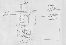
This should explain it. There are a couple of white tape pieces whose edges might look like lines. Ignore them.

Seat heat wiring diagram003.jpg

If you look closely at the picture, especially the one on Amazon, you'll see a black wire with a stripped end. That goes to ground, preferably a good battery ground lead. The red is fused battery power. The yellow goes to switched power to light the switch.

When the switch is in HI position both heater pads connect to power and to ground because the relay coil is energized. Heater 2 receives power through the relay when its coil is energized. When the switch is in LO position the common ground from both pads is broken, the relay coil is not energized, and Heater 2 power end connects to ground putting the heaters in series. Note that the relay handles the power side of the heaters and the switch handles the ground side of the heaters.

The BRP switch can be used. The one big difference between it and the kit supplied switch is the BRP switch indicator light is on any time the ignition is on, just like the other dash switches. The kit switch has a two color LED or two LEDs to show when the switch is in HI or LO position. To use the BRP switch the indicator LED will need to connected to ground by a wire that is not in the heater kit.

Billy, I'll let you figure out which of the kit switch spades needs to go to which BRP switch terminal and where the best place will for Spyder to tap into main power, switched power, and ground. I need to get ready to leave home for a couple of weeks!
 
You may have missed some of the things Spyder Hawk told us. The relay has only 4 wires going to it. Your diagram has 5. The yellow switched source wire goes to the relay. Not the switch.

One of the wires going to the switch is a ground. The black one. As mentioned in a previous post.

If you read post 39. He has the power, switched power and ground connected to good locations.
 
You may have missed some of the things Spyder Hawk told us. The relay has only 4 wires going to it. Your diagram has 5. The yellow switched source wire goes to the relay. Not the switch.
In post 30 he says there are 3 blacks, two reds, and one yellow going to the relay. There is no way I can see how you can have Lo/Hi heat without using all 5 terminals of the relay. The wiring diagram I used to try to figure this out is in this installation instruction. It's for a similar kit but without the yellow switched wire. https://www.google.com/url?sa=t&rct...allation.pdf&usg=AOvVaw3fJ3eJ975-I7AWmvxTKYgf.

I give up! I don't have any more time to work on this. As far as not staying on when the ignition is turned off I believe his kit is intended for auto use with main power coming from a switched source. He used the word illumination for the yellow wire which indicates that wire connects to the car lights so the switch will be illuminated at night. I'm sure the switch has internally wired LEDs to indicate when the heater is on.
 
I don't see where it could be connected to all 5. Unless it is done so inside the relay. The center pin is not used for some reason. The seller agreed to send me another harness and switch so when it gets here I'll be able to cut one open and then you all can see what is what. It all works the way it is just not dual heat. That and I want to make sure it is right because I don't want to become a ball of flame on the side of the road.
 
There is also a 5th pin on the relay that is not connected to anything.
View attachment 182341
The one in the center.
WOW, lots of discussion on this one, that's great.

However, all this discussion and I did not see anyone address your concern about the pins on the relay.

Four of the pins will have numbers: 30, 85, 86, 87. The center pin will also have a number, and the number will tell you what it does. Is that center pin #87 or #87a?

In a typical wiring diagram, 85 or 86 will be the trigger for the relay, the other pin will be the ground. Pin #30 will be the power in and #87 is the switched power out.

If the center pin is #87, it is simply a second switched pin that comes on at the same time as the other one. Very handy when connecting something like fog lights or driving lights, you connect one light to each terminal. If the center pin is #87a, it will be ON when the #87 pin is OFF. Power from #30 will go to one or the other, but not both.

.

Did you notice the schematic for the relay? It's printed on the relay and is in one SH's picture.
 
I just checked something. The heated grips are the same two stage heating elements aren't they? When I check that switch it shows ground at 12v and the light illumination post at 7v. Does that mean anything or am I just charging at windmills?
 
WOW, lots of discussion on this one, that's great.

However, all this discussion and I did not see anyone address your concern about the pins on the relay.

Four of the pins will have numbers: 30, 85, 86, 87. The center pin will also have a number, and the number will tell you what it does. Is that center pin #87 or #87a?

In a typical wiring diagram, 85 or 86 will be the trigger for the relay, the other pin will be the ground. Pin #30 will be the power in and #87 is the switched power out.

If the center pin is #87, it is simply a second switched pin that comes on at the same time as the other one. Very handy when connecting something like fog lights or driving lights, you connect one light to each terminal. If the center pin is #87a, it will be ON when the #87 pin is OFF. Power from #30 will go to one or the other, but not both.

.

There is a picture of the top of the relay. It has an internal diagram of the relay and the center pin is marked 87a. Point is mute since that pin is not being used anyway.
 
In post 30 he says there are 3 blacks, two reds, and one yellow going to the relay. There is no way I can see how you can have Lo/Hi heat without using all 5 terminals of the relay. The wiring diagram I used to try to figure this out is in this installation instruction. It's for a similar kit but without the yellow switched wire. https://www.google.com/url?sa=t&rct...allation.pdf&usg=AOvVaw3fJ3eJ975-I7AWmvxTKYgf.

I give up! I don't have any more time to work on this. As far as not staying on when the ignition is turned off I believe his kit is intended for auto use with main power coming from a switched source. He used the word illumination for the yellow wire which indicates that wire connects to the car lights so the switch will be illuminated at night. I'm sure the switch has internally wired LEDs to indicate when the heater is on.

Your diagram looks like it should work. Just not what's happening here.

Yes there are 6 wires going to the relay plug. But the 3 black wires go to the same pin. So it's a junction for the black wires. As seen in one of the pictures. Also from that same picture it is also visible that the center pin is not used.
 
It's kind of working now. I can't really tell how hot it is getting because it is so hot outside. It will be a few weeks until the new harness and switch get here so I'll take a step back from it for now. When the new harness gets here I will redo the bike and then gut the old harness so we can see what is going on. Thanks so much everyone for your knowledge and time. I'll let you know back in this thread when the harness gets here.
 
Back
Top