• There were many reasons for the change of the site software, the biggest was security. The age of the old software also meant no server updates for certain programs. There are many benefits to the new software, one of the biggest is the mobile functionality. Ill fix up some stuff in the coming days, we'll also try to get some of the old addons back or the data imported back into the site like the garage. To create a thread or to reply with a post is basically the same as it was in the prior software. The default style of the site is light colored, but i temporarily added a darker colored style, to change you can find a link at the bottom of the site.

Need a Wiring Diagram - for a seat heater?

Spyder Hawk

Member
I have an extra grip heater switch and I wanted to use it for a seat heater. I can't find any kind of wire diagram for it. Do you know what wires go where. I have ...
Red ( I assume is power )
Yellow ( switched power for illumination )
Black ( Ground )
White

The heater didn't come with instructions and all the ones online have it with a pre wired switch. I tried it ( left to right )
Red+Yellow
Black
Black ( Jumper from the other black )
White

It lights up, and gets hot but it stays on without the switch. Any help or a point in the right direction would be great.

IMG_2828.jpg
 
Last edited by a moderator:
Educated guess without looking it up. See picture below.
2 pins marked 1. Switch backlighting. Connect one pin to 12V running light circuit. Other to ground.
Pin marked 2. 12v to high heat element on grips.
Pin marked 3. 12V to the switch.
Pin marked 4. 12V to the low heat element on grips.
 

Attachments

  • switch.jpg
    switch.jpg
    47.9 KB · Views: 11
Well, that didn't work. I went to the manufacturer of the switch, Carling Technologies, and they had a lot of information. All of which was no use to a person like me. All I found was that it was a Contura 2 V6D2 switch but they had no wire setups to look at.
The switch that came with it has 4 wires, red, yellow, black, and white. It has another yellow wire of smaller gauge running outside the harness that is supposed to go to a switched power line. When I attach it I hear the relay in the harness turn on. I didn't think that a rocker switch would be this hard to figure out.
 
Would expect BillyBovine to be close.
An illuminated switch may be powered separate or connected to power.
It can be illuminated to locate it at night, or can can be lluminated according to position energized.
Can you identify the switch in this PDF link?

https://www.carlingtech.com/sites/default/files/documents/V-Series-II-III_datasheet.pdf

Page 6 has different configurations on page 8 the "schematic".

To verify or just test, connect test leads to 12 volt source and probe switch connections with voltmeter.
Connect + probe (hopefully alligator clip) to the one you think may be power, then check for voltage at other positions, in all switch configurations with negative probe.
You'll figure it out.

Is seat heater two levels of heat?
If so, it should have high, low and ground wires.

A resistance test should indicate who is who.
Can explain further, if requested.
 
The switch is the heated grips switch. I had an extra one and thought I would use it for this oh so easy project, lol. The seat heater is two levels and came with a switch but it is too small to fit in the hole already cut in the tank cover.

https://www.amazon.com/gp/product/B00RZL667I/ref=ppx_yo_dt_b_asin_title_o07_s00?ie=UTF8&psc=1

The problem is the factory switch has 5 wires running to it. When the spyder is on, not started, the only one that shows power is the number 1a pin ( The one on the left top ). The other seems to be ground so that leaves me with 3 pins. I assumed Yellow and White but that leaves me a wire short. Unless I am supposed to run another power to it. I also don't get where the relay figures into all this. The yellow is coming from the relay I take it.

switch.jpg
 
The switch is the heated grips switch. I had an extra one and thought I would use it for this oh so easy project, lol. The seat heater is two levels and came with a switch but it is too small to fit in the hole already cut in the tank cover.

https://www.amazon.com/gp/product/B00RZL667I/ref=ppx_yo_dt_b_asin_title_o07_s00?ie=UTF8&psc=1

The problem is the factory switch has 5 wires running to it. When the spyder is on, not started, the only one that shows power is the number 1a pin ( The one on the left top ). The other seems to be ground so that leaves me with 3 pins. I assumed Yellow and White but that leaves me a wire short. Unless I am supposed to run another power to it. I also don't get where the relay figures into all this. The yellow is coming from the relay I take it.

View attachment 182266

It would undoubtedly be your worthwhile to buy a service manual. www.canammanuals.com Looking at the wiring diagram one pair of tabs is for power and ground for the indicator light. That is powered when the ignition is on. The other 3 are a two way switch configuration. Power in to the common tab from the load shedding relay so the motor must be running to see that power. The other two tabs are for high heat and low heat heaters in the grips.
 
So, 1a, top left is ignition or otherwise switched power to the switch. If for backlighting, as already suggested, is switch illuminated?

Are you indicating that 1 is a ground? If so, why? Is resistance to ground just under zero ohms (~0.1). If so, that ground would be for illumination, as already suggested.

Explain wire short. Heater can be grounded independent of the switch or joined to 1, if verified ground. There are 1/4" spade adapters to plug 2 into 1, if you do not want to splice.

When switch is operated, which pins get voltage in what switch position?

If the above is correct about illumination, let's review suggestion by billybovine:

2 hi
3 common
4 lo

One of these need to have power when key is on, unless there is a relay that is not energized until engine actually started.

Pls check that.

With engine on, which of those 3 have power, regardless of switch position?

Sorry to not have schematic to help easier.
 
One of these need to have power when key is on, unless there is a relay that is not energized until engine actually started.

With engine on, which of those 3 have power, regardless of switch position?
.
That is the case. The heated grips are powered by the load shedding relay which closes only after the engine is started. The BRP heated seat connects into the harness between the switch and the handlebar heated grips. Same with the passenger heated portion of the seat. The common terminal on the switch will be the one powered.

So Spyder Hawk, this begs the question. Why are you wanting to use this extra switch? Is this a BRP or aftermarket heated seat? If BRP connect it to the grip heater circuit like BRP intends. If it's after market did it not come with a harness and switch? Or do you just not want, or can't, use the switch that came with the seat? How about buying the BRP harness as a repair part and use it to power your seat? Did you say you have no schematic for the seat at all? If so, have you figured out which wire does what on the seat? You need to be sure of that first. Then figure out how to connect the switch to it. Where are you planning on tapping in for the main power for the seat?
 
...The switch that came with it has 4 wires, red, yellow, black, and white. It has another yellow wire of smaller gauge running outside the harness that is supposed to go to a switched power line...

I would expect the 4 aftermarket heater wires to be
hot (via relay)
hi
lo
ground

Energizing with a fused lead from a battery would sort out who is who.

Is the smaller yellow wire an assumption or is there some indication, not yet mentioned of its purpose?

Do you have a VOM-multimeter?
 
...Why are you wanting to use this extra switch? Is this a BRP or aftermarket heated seat? If BRP connect it to the grip heater circuit like BRP intends. If it's after market did it not come with a harness and switch? Or do you just not want, or can't, use the switch that came with the seat?

See post 6
 
I am without a voltmeter. I have not blown any fuse's yet so that is a good thing. All this advice is giving me ideas of what may be wrong. Does this make sense to you...
1a. Power: from another source on the bike
1. Ground: from the wire harness of the heater
2. Red: High
3. Yellow: from the relay
4. White: Low
5. Thin Yellow: To secondary source for the light.

Wait, hold it, stop! I'm beginning to think you really don't know what you are doing. Sorry! First you must determine and explain what wires come from the heater, how many and what roles they play. If you don't know for sure then you must get a VOM to chase down the circuits. Next, what and where is the relay, and what does it do, control the power to the heater? And where is it, attached to the harness or buried inside the seat? Once we know what those wires all do then we can determine what role you want the grip heater switch to play and how it needs to connected. Plugging wires in somewhat willy nilly will get you into trouble. Explain how the supplied switch you don't want to use is connected into the harness.

For any project to be successful you must know where the start is, and what you want the end result to be. Then you can determine how to get from here to there. Right now you haven't made clear what the start is. Until you do that you can't get to there.
 
Well, nothing worked. When the engine is on the factory switch is suppose to behave like this ( see pics )
Engine on: 1a and 3 have power
IMG_2833.jpg
IMG_2834.jpg

In the HI Heat position: 1a, 3, and 4 are on
IMG_2833.jpg
IMG_2835.jpg
IMG_2836.jpg

In the LOW heat position: 1a, 2, and 3 are on
IMG_2833.jpg
IMG_2838.jpg
IMG_2837.jpg

The Carling website said that the number 1 pin was for the illumination ground only. Is the number 3 pin also suppose to be a ground? I'm trying to find another switch but nothing fits in the hole and I need a two position switch. Everything around me is on / off only. I would like to use the switch I have but it seems it can't be wired to operate such a simple device.

This is the harness for the heater. Simple 4 connection rig. Red and black power the pads with a plugin pigtail. 2 Blacks, yellow, and 2 reds go into relay. Red, black, yellow, and white go to switch. Lone light yellow wire, I was told, goes to a switched power.
sh.jpg
IMG_2841.jpg
IMG_2840.jpg
IMG_2839.jpg
IMG_2842.jpg

I hope some of this makes sense. I'm a little out of my depth here. I'm recovering from a stroke and a fractured back so I figured now would be a good time to do these little projects.
 
Pin 1A has power with key on. Engine running not needed. That power is from the running light circuit to power the switch light only. Has nothing to do with powering the heated grips.
Pin 1B is ground. It is there to complete the circuit for the switch light. Not used for anything else. Has nothing to do with the heated grips.

The operation of the heat grips only uses 3 pins on the switch. Power from the Spyder is fed to the switch on pin 3 (common). Only live when the engine is running. The switch position controls whether the power goes to pin 2, 4 or off.

I don't know why there is a relay in the harness for heat pads you have. Need more info. But if you look at the heating pads. They will each have 2 or 3 wires. Likely 3 because they have 2 heat levels. If only 2 that will make it more interesting. So one of the 3 wires will be low heat. Connect to pin 2 on the BRP switch. Another will be for high heat. Connect to pin 4 on the BRP switch. The third wire will be common ground. Stop trying to connect the ground to the switch. It needs to be connected to chassis ground.
 
After some more googling. It is more likely that pads only have 2 wires each. When the pads are connected in series they output low heat. When connected in parallel they output high heat. That is why there are more wires on the switch. I would think that a double pole switch is what is on the heating pad harness. The BRP switch is only a single pole. Still could be made to work with the BRP switch, but only one heat setting. That I don't think would be ideal.
 
Now we're making progress! :thumbup:

First, what year and model is your Spyder? Wiring is different for different models.

Another question. The grip heater switch you show, are you plugging into an existing connector intended to be used for a seat heater, or are you splicing into the Spyder wiring? Is the green connector part of the Spyder harness? Is it used for the grip heaters and you're just using it for testing, or is it an extra connector?

Looking at the pictures you're having trouble because the wiring for the heater, as I see it in the pictures, is screwed up. Have you had the harness uncoiled? If not, do so. You should have, probably, a red wire and a black wire with tab connectors on their ends. You need those for power and ground to be connected from the heater package into the bike wiring. Or is that what you show in the next to last pic?

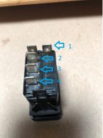
Is the heater supposed to be high and low heat using both pads on the driver seat, or one heat level only with one pad for driver and second for passenger? Where did you get the heater? What is its brand and model, or do you even know? Is the included switch simple on/off, or is it on/off/on, i.e., two on positions? A pic of its terminals will clear that up.

The yellow wire goes to switched bike power. When you flip the switch the relay energizes which is what controls power to the heater pads. Please unplug it and post a photo of its terminals, and a close up of the wires plugged into it.

Well, nothing worked. When the engine is on the factory switch is suppose to behave like this ( see pics )
Engine on: 1a and 3 have power

In the HI Heat position: 1a, 3, and 4 are on

In the LOW heat position: 1a, 2, and 3 are on

The Carling website said that the number 1 pin was for the illumination ground only.

That's right. #1 connects to Spyder ground.
Is the number 3 pin also suppose to be a ground?
No! 3 is connected to the main 12 volt power supply of the bike.
I'm trying to find another switch but nothing fits in the hole and I need a two position switch. Everything around me is on / off only. I would like to use the switch I have but it seems it can't be wired to operate such a simple device.
Do you mean you want an ON/OFF switch, or an ON/OFF/ON switch? You have a two position switch in your hand! It's two position in the 2 to 3 position, i.e. on/off, and two position in the 3 to 4 position, also on/off. You can use it with no problem. The only difference from your other switches is when you have 2 to 3 used you have two OFF clicks, on in the middle and the other with the switch in the 3 to 4 position. Use either 2 or 4 to go to the heater, whichever one is connected when the switch is pushed at the top.
This is the harness for the heater. Simple 4 connection rig. Red and black power the pads with a plugin pigtail. 2 Blacks, yellow, and 2 reds go into relay. Red, black, yellow, and white go to switch. Lone light yellow wire, I was told, goes to a switched power.

I hope some of this makes sense. I'm a little out of my depth here. I'm recovering from a stroke and a fractured back so I figured now would be a good time to do these little projects.

I'm thinking you may have a high/low heat heater pad in which case you need a three way switch like you have. But the relay wiring conflicts with this idea. That's why we need more info.

Also a good time to learn! How much electrical wiring experience to you have? Are you perchance having problems grasping all this because of the after effects of the stroke? If so, we'll work on this more slowly and methodically. We may even need to just start over and carefully take things one step at a time. The stroke can be a very justifiable reason for difficulties grasping concepts such as what is involved here.
 
Yep, the stroke definitely took some of my overall skills with it. High School electronics with Mr. Lillo was not my strong area of study that is for sure. I really appreciate all of the help you guys. I think I'm going to put the supplied switch on and make sure it works first. I just assumed it was working because it was new. I'll let you know tomorrow when I get it set up. I don't like it when things that are supposed to work don't. It makes me more determined to fix it. Thanks again.
 
By the way I have a 2013 Spyder ST-S that has been upgraded to an ST-Limited if that makes any difference.

The seat heaters have their wire harness and relay. I was using the empty connector, Orange one, for the connector. It was for the air compressor to the rear shock I think. The ST's don't use it so it was free. I removed all the spade connectors so I could put my own wire configuration in it.

The last two pics are of the wires that were out of the supplied switch. Aside from that there was two wires, red and black, that are going to the bikes battery. The power line also has a 10AMP fuse in it.

Yes it is a Hi and Low on both pads at the same time. I put one on the drivers seat and one on the passengers seat. The supplied switch is an On-Off-On switch which, I thought, would be the same as what the other switch was. I suppose wiring a switch can be very complex depending on what you intend to do with it. I have read that BRP engineers are a bit all over the place when it comes to wiring. On the heated grips there is an Orange and Black wire and then all the others are green, lol.

All the wires converge at the relay and are sealed up so I can't see what they are doing in there. I'll get more pics.
 
Back
Top