Deseret Rider
New member
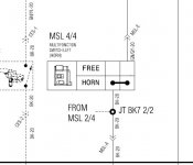
Can anybody give me a link to a wiring diagram so I can help him solve his turn signal problem--(Neither side will work) -All fuses and bulbs are good---we can't find a 'flasher' unit? (Don't see one listed on the fuse box lid and can't otherwise identify one anywhere). I have some electrical savyy but no schematic to follow and I do not have any Can Am experience so any help or advise would be much appreciated Lynn
PS---reply here or by PM----thanks in advance.
PS---reply here or by PM----thanks in advance.