• There were many reasons for the change of the site software, the biggest was security. The age of the old software also meant no server updates for certain programs. There are many benefits to the new software, one of the biggest is the mobile functionality. Ill fix up some stuff in the coming days, we'll also try to get some of the old addons back or the data imported back into the site like the garage. To create a thread or to reply with a post is basically the same as it was in the prior software. The default style of the site is light colored, but i temporarily added a darker colored style, to change you can find a link at the bottom of the site.

Fused electrical distribution block

ozarkryder

New member
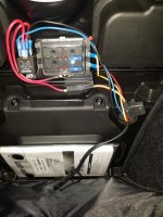
Bunch of mods listed in my profile, the one that is a DIY is a fused distribution block under the zippered lining in the frunk of our RT limited. I have run this in some fashion on 8 or 9 former motorcycles to run accessories directly off the battery. It is controlled by the ignition with a solenoid energised by a hot wire that is only on when the key is on. On most past bikes anything that came on with the key could be tapped, but I usually used the license plate light feed, as if something goes bad and the circuit gets messed up the only thing affected is the license plate light. With the newer CAN-bus we have to be more careful on where to tap in. On our RT Limited there is an unused feed into the frunk behind a rubber plug to add a power tap to the left of the battery. There is a hot and ground lead and it is on when the key is on, a great place to energize a relay. If I want to add a power tap in the frunk I can use one of the fused connections on the fuse block. I only run hot wires from the block, for the ground I use a handy metal-to-metal frame bolt close to the installed outlet. Here is a picture:
Spyder powerblock 2.jpg
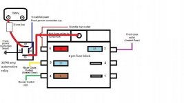
The black wire hanging in front of the manual is a fused direct to battery charger/maintainer connection.The '18s have the battery behind a panel in back of the owner's manual, and the fuse is back there just above the battery. The red wire that turns yellow behind the tape is fused from the battery to the solenoid, I have added 2 more outlets, therefor 2 more sets of wires and fuses than shown.The wires come through the rubber bung that covered the hole in the frunk wall. I made a hole in the middle and a slit from the hole to the edge. The hole is just big enough to fit the wires and pretty well seals the inside from the elements. As I add more wires I have to make the hole a little bit larger. Here is a diagram:
Spyder powerblock 1a.jpg
Looks like you'll have to click and open the pictures in a new window to make them big enough to see clearly.
 
Last edited:
I can't find the lead to drive the solenoid

Ozarkrider,

I just got a 2018 RT Limited. I took the rubber plug out and couldn't fine the switched power lead. I even took out the battery and I still can't find it. It's got to be there somewhere but it is not obvious to me.

Your setup looks like an excellent solution.

Maybe I'll take it to the dealer and ask them to find it for me. If I have a 2018 it should be there somewhere.

I have a 2018 Service manual and the wire is on the wiring diagram.

If you have any suggestions I would love to hear them.

Thanks for any help,

Gridley
 
This will help during the next winter when I add a bunch of electronics, GPS, Heated gear, USB connection on the wheel, aftermarket horn, LED light bar (if I can find a good place for it), etc.
 
I have a relay for LEDs, and a fuse block like the pictured one for any high amp draw farkles that I might add in the future. The previous owner installed a dual USB port in the speaker grill and a volt meter on the right side speaker grill. But he ran a double fuse line and cut a notch in the right side fuse block and connected to ACC Keyed fuse. I just came in behind the fuse block and T-Tapped into the wire back there. The Nanny won't object because it's a original equipment ACC spot.
 
Excellent! This is exactly what I do, although I positioned the marine fuse block in a different place. The other thing this can allow is the use of LED turn signal strips that blink WITH your OEM turn signal lights, eliminating that confusing alternate flashing ;) Nice job explaining, BTW :thumbup:
 
ozarkryder, thank you for the info.

I am planning to put my FZ-1 in the same spot. I have already wires installed, we took off the frunk to pull the hidden zipped optional plug out and fed this plug through the grommet hole together with new wires. I have male quick connect on the end of the switched wire from the fusebox to the optional plug. All meter tested and ready.

I am thinking to glue some plate to the wall in the middle between the two Spyder's fuseblocks - very similar to yours. I want to possibly fill in the voids with black silicone caulk for added stability behind the plate and Velcro the FZ-1 to the plate. I am not sure if this is a good option. How did you secure your plate to the wall"
How did you secure your fuse-box?
 
I did basically the same thing except I put 2 relays behind the left body panel.I run wife’s heated vest off 1 relay and the other is for the Wolo horn.I have extra spots for future accys
 
Ozarkrider,

I just got a 2018 RT Limited. I took the rubber plug out and couldn't fine the switched power lead. I even took out the battery and I still can't find it. It's got to be there somewhere but it is not obvious to me.
Look for a wire doubled over with a rubber boot covering it all and cable tie wrapped into a tight bundle. It might be tie wrapped to the frame.
 
Handy little devils, and saves trouble if you have a dozen circuits you want to isolate. Makes it a whole lot easier to track down any problems. This one had fault indicators built in ... If the lights on, that circuit needs attention.

fuse-box.jpg


PS - I got the bike used. Prior owner had added all sorts of electronics to it, and I had a real hodge podge of twisted wires and such. Kind of a "where's waldo?" thang going trying to track down all the inline fuse holders scattered about.
 
Yup, a fuse block is the only way to go when adding electrical accessories. I've read here too many who have had their bike's electrics go wonky when they didn't use one.
 
Oops! That is not a power distribution box. It's used to connect trailer wiring to the bike wiring. It is an isolation module to protect the bike wiring from problems in trailer wiring.

While it could be used for trailer wiring it could also drive additional add on lights. Plus, it has 5 additional available circuits 3-switched and 2-always on. Nice little box.
 
While it could be used for trailer wiring it could also drive additional add on lights. Plus, it has 5 additional available circuits 3-switched and 2-always on. Nice little box.
OK, I see it now. If one is going to add an after market trailer harness and either add, or make provision for, other accessories at the same time then that unit makes sense. It gets the switched signal from the running light circuit. But if you already have a trailer hitch and harness installed, or plan to install the BRP one, then this unit wouldn't make sense, especially for $125.

Using the terminals on the side opposite of the the keyed and hot power terminals, for additional add-on lights won't work, unless those lights are additional turn and brake lights. That's because the relays that power the light output wires are triggered by the bike light circuits, i.e., left turn, right turn, and brake.
 
Where did you get your fuse block? I like the idea of fault testers but haven't seen that on the fuse block I've looked at.
 
Back
Top