• There were many reasons for the change of the site software, the biggest was security. The age of the old software also meant no server updates for certain programs. There are many benefits to the new software, one of the biggest is the mobile functionality. Ill fix up some stuff in the coming days, we'll also try to get some of the old addons back or the data imported back into the site like the garage. To create a thread or to reply with a post is basically the same as it was in the prior software. The default style of the site is light colored, but i temporarily added a darker colored style, to change you can find a link at the bottom of the site.

F3 S fog lights staying on regardless of switch - what's wrong with this picture?

OK-DZ9R

Member
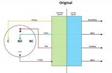
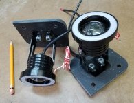
I built a set of fog/driving lights for my 2015 F3 S. Lights, hardware, switch and a plastic cutting board all together cost about $35. Using this wiring schematic I found on this forum I wired the switch which is supposed to be the way Can Am and Lamonster wire it. However, the light stays on while the engine is running no matter if the switch is in the off or on position. Any ideas what the problem is? I've tried 3 different switches and get the same result.


CanAm FogLight-M.jpg

SpyderSWITCH-6bM.jpg
 
I built a set of fog/driving lights for my 2015 F3 S. Lights, hardware, switch and a plastic cutting board all together cost about $35. Using this wiring schematic I found on this forum I wired the switch which is supposed to be the way Can Am and Lamonster wire it. However, the light stays on while the engine is running no matter if the switch is in the off or on position. Any ideas what the problem is? I've tried 3 different switches and get the same result.
.....

So from what you tell us ^^, I'd guess that it's NOT the switch that's the problem, but more likely the way you've wired it..... :rolleyes:

Without actually seeing the switches you've used and looking at how you've physically wired it all up, the following is gonna be a bit of a WAG, but who knows, it might help...:dontknow: And even if it might seem like trying to tell some of you how to suck eggs, there's obviously a need for it, or the question wouldn't have been asked! So I'm sorry, OK & any other readers if it's belabouring the obvious, or if it seems like it's too simple a concept, I'm only doing my best at helping here... :opps:

At it's most basic, electrical power will only work if there's a complete circuit - power from one battery terminal going out to where it's needed and coming back to the other battery terminal. All a switch does, is to interrupt that so that you can select to have your light ON or OFF. In this instance, you don't really need to worry about anything else, just the power going out to the lights and then going back to the battery. If you can't envisage that loop with the switch being the interrupt that opens to break the loop or closes to complete the loop, or circuit, then it isn't going to work! So look at the switch & its wiring diagram/schematic (not the wiring diag you got off the Forum, wasn't there one specifically for the switch that came with it?? :dontknow: ) it seems to me that you are most likely connecting your +/- power to the light wires across a pair of 'always connected' terminals on the switch, and since it's called a 'SWITCH', there's gotta be some terminals/way of connecting those light +/- wires across the switch in a way that turning the switch OFF will actually disconnect those wires/interrupt the power flow to the lights - at the moment, with the way you've connected each of those 3 switches so far, it seems that you haven't been interrupting the power supply to the lights with the switch at all, and you need to! :lecturef_smilie:

Do you have a multi-meter so you can check the continuity across the terminals you've been using as the switch changes position? If not, get one - they aren't expensive & there's usually basic instructions that come with them! They make troubleshooting things like this possible & relatively easy, but without them, you're playing 'stab me in the dark'!! So if you use a multi-meter or even just an indicator light and there's continuity/a connection across the wires between the lights all the time, regardless of whether the switch is in the ON or OFF position, then you're wiring it incorrectly! Is there another unused terminal on the switch?? If so, have you tried using that?? Might be a good idea to check the continuity first, and look for power that's only there when the switch is ON, but still :dontknow: There hasta be some way of connecting the 'switch' that leaves you with a broken circuit/no continuity to the lights when the switch is in the OFF position, you just haven't found &/or used that yet & THAT's the answer to all this! :ohyea:

Hope that's at least a little clearer'n mud.... Good Luck! :cheers:
 
Last edited:
The fog lights I installed have 2 modes. There is a running light mode (just the outer ring), which stays on any time the engine is running. Then they have the full fog light mode which is controlled by the switch. My lights were from a kit with the switch included and plugged right into the existing OEM wiring harness.

Do the fog lights you used have one mode or two modes?

There is a slight chance the wiring diagram that came with my fog lights could still be in the shop, but only a slight chance.

I don't remember where I got the fog light kit from, but pretty sure it was one of the advertisers on this website.
 
Thanks all for the help. I apologize that this is a bit long.
I do own a multimeter and have somewhat of a grasp of basic electrics, which might be my downfall here. I’m using a SPDT latching on/off switch with one normally open and one normally closed connector and a LED lighted power indicator ring. I’ve connected this switch to the stock Can Am wiring that is under the switch blank on the dash using a standard JAE MX 1900 female connector. So far so good. The way Can Am sets it up, the LED switch lighted ring is on all the time while the engine is running no matter if the switch is on or off and that’s the way it is working. Some people hate this, but it’s no big deal to me. The fog/driving light part of the switch only triggers a relay which in turn powers the lights and there’s the problem. Although it appears that I have this wired correctly — There are only four wires and two of them are grounds. One is a blue/white wire that corresponds to the blue/white wire at the light and is wired to the C connector the black ground next to it is wired to the NO connector.
The lights are on while the engine is running no matter the switch position. My first thought is that the relay is stuck, but I have no idea where that is or if it is a mechanical or solid-state relay. I would expect a solid state one which would not be stuck and deepens the mystery.
The lights I have installed have angel eyes which I have wired to the customer circuit behind the frunk and are running as DRLs. I could bypass the stock wiring for the fog lights as many others have done or live without them, but I just hate an unsolved problem. I guess I need to dig out my multimeter.
 
It sounds to me like you have a mix up in your regulator wires. Check the diagram that came with that, maybe that is where the problem lies.
 
I do some of my best thinking in the middle of the night. At three a.m. this morning this occurred to me: Can Am's accessory fog lights have halogen projector bulbs. I'm using LED lights on the provided wiring. Are the LEDs not pulling enough amps to trigger the relay?
Maybe I will use the customer wiring on the left side if I can reach it. I have seen it but it is buried deep.

The customer wiring plug should be just tied or taped to the other wiring bundle in there. Once you clip it loose, you should have plenty of length to pull the plug out and get to it.
 
I went to trade school growing up .... I've ( successfully ) wired two houses I built ...... I can't address what's happening inside those PLUGS .... from the pictures .... the separate red & white wires control the " angel eye " just wire them directly to a power wire that has power ONLY when the engine is running & a ground wire .... they will stay lit after the bike is running ..... The wires in the black harness should only activate the actual FOG LED ... black goes to any ground .... the red wire goes to one terminal on the switch, the other switch terminal needs a wire to a power wire. .... this LED will only go on if the switch is used .... hope this helps . .....keep us informed .... good luck .... Mike :thumbup:
 
I went to trade school growing up .... I've ( successfully ) wired two houses I built ...... I can't address what's happening inside those PLUGS .... from the pictures .... the separate red & white wires control the " angel eye " just wire them directly to a power wire that has power ONLY when the engine is running & a ground wire .... they will stay lit after the bike is running ..... The wires in the black harness should only activate the actual FOG LED ... black goes to any ground .... the red wire goes to one terminal on the switch, the other switch terminal needs a wire to a power wire. .... this LED will only go on if the switch is used .... hope this helps . .....keep us informed .... good luck .... Mike :thumbup:

I have the Lamonster fog lights for my 2022 F3s. They are installed per directions and connected to the fog light connectors standard on the bike. The switch that was provided with the kit is lite at all times whether the lights are on or off.
 
Hi All. I installed these same light as OK-DZ9R on my Ryker. I wired the ring to the auxiliary wire and the main light to the battery. So now the ring is on when the bike is running and the main is on by a switch for night riding.
 
Back
Top