kentompkins
New member
What follows is a written and photo description of how to make the electrical connections between a 2008 RS Spyder and a 2010 BRP trailer. If anyone, following these instructions, has questions, please write me at the email address below.
I recently purchased a used 2010 BRP trailer. I have a friend who is an expert in wiring, soldering, electronics construction and solving big problems in small spaces. He agreed to wire-up my Spyder and the trailer.
After reviewing the wiring diagram in the BRP Trailer Service Manual and the suggestions I found here, he decided to use a Hopkins Vehicle Converter Kit #46255. This kit isolates the Spyder's electrical system from problems caused by the hook-up.
The kit is a small circuit box with a four wire connector and positive and negative wires to connect to the Spyder's battery. The color scheme is:
Red wire (large) ----- Battery
White wire ----- Ground
Brown wire ----- Park/Tail
Yellow wire ----- Left turn
Red wire (small) ----- Brake
Green wire ----- Right turn
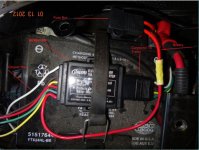
These can be seen in this photo. We located the Isolator unit under the battery strap for stability and proximity to terminals.
The first step after securing the unit, was to connect it to the positive and negative terminals. We also crimped the fuse box to the positive lead; you can see the yellow crimp. I've marked the fuse box at the top but, being black, it is a bit hard to see.

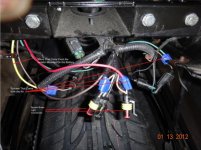
In Step Two, I will illustrate how to connect the various colored Isolator wires to the Spyder connections.
I recently purchased a used 2010 BRP trailer. I have a friend who is an expert in wiring, soldering, electronics construction and solving big problems in small spaces. He agreed to wire-up my Spyder and the trailer.
After reviewing the wiring diagram in the BRP Trailer Service Manual and the suggestions I found here, he decided to use a Hopkins Vehicle Converter Kit #46255. This kit isolates the Spyder's electrical system from problems caused by the hook-up.
The kit is a small circuit box with a four wire connector and positive and negative wires to connect to the Spyder's battery. The color scheme is:
Red wire (large) ----- Battery
White wire ----- Ground
Brown wire ----- Park/Tail
Yellow wire ----- Left turn
Red wire (small) ----- Brake
Green wire ----- Right turn
These can be seen in this photo. We located the Isolator unit under the battery strap for stability and proximity to terminals.
The first step after securing the unit, was to connect it to the positive and negative terminals. We also crimped the fuse box to the positive lead; you can see the yellow crimp. I've marked the fuse box at the top but, being black, it is a bit hard to see.

In Step Two, I will illustrate how to connect the various colored Isolator wires to the Spyder connections.

