• There were many reasons for the change of the site software, the biggest was security. The age of the old software also meant no server updates for certain programs. There are many benefits to the new software, one of the biggest is the mobile functionality. Ill fix up some stuff in the coming days, we'll also try to get some of the old addons back or the data imported back into the site like the garage. To create a thread or to reply with a post is basically the same as it was in the prior software. The default style of the site is light colored, but i temporarily added a darker colored style, to change you can find a link at the bottom of the site.

Didn't last a week!

I have a flash to pass somewhere that I can use. If you can share just that diagram on the acc switch, that would be great.

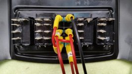
I can't seem to attach the wiring diagram I drew up, but for the exact switch that I used here is what I did:

Battery positive from the wires in the frunk that would plug into the optional power outlet goes to pin 3 on the switch. (This way the power is switched off with the key if using fuse F6)
Jumper from pin 3 to pin 6 and also to pin 8 if you want the switch internal light to work.
Pin 7 to ground if you want the light to work. (This only provides ground for the internal light)
Pin 2 sends the positive to my aux fuse box when the switch is in the ON position.
Pin 5 sends the positive to my garage door opener when the momentary is pressed.

attachment.php
 

Attachments

  • switch wiring.jpg
    switch wiring.jpg
    45.8 KB · Views: 659
Last edited:
I can't seem to attach the wiring diagram I drew up, but for the exact switch that I used here is what I did:

Battery positive from the wires in the frunk that would plug into the optional power outlet goes to pin 3 on the switch. (This way the power is switched off with the key if using fuse F6)
Jumper from pin 3 to pin 6 and also to pin 8 if you want the switch internal light to work.
Pin 7 to ground if you want the light to work. (This only provides ground for the internal light)
Pin 2 sends the positive to my aux fuse box when the switch is in the ON position.
Pin 5 sends the positive to my garage door opener when the momentary is pressed.

attachment.php
Thanks
 
Jetfixer,

Very nice initial mods. Thanks so much for sharing. The information about the Carling Contura switches was especially useful,and I'm sure very much appreciated by many here. :thumbup:

Welcome to the forum, and hope to see a lot of posts from you about future mods, etc.

If you don't mind a personal question... does your username imply that you are a jet aircraft mechanic, when you are not riding your new Spyder?

Yes. I work for the new American Airlines (formerly USAirways)
 
Jetfixer,
I just retired from AA last Aug.
I was a pilot. Glad to be out of the rat race!

Sent from my SM-G920V using Tapatalk
 
Great info on the switch. I have a Flash2Pass I was going to install but then didn't want to because of the mechanical high beams. I thing I want to take an existing GDO remote and mount it probably in the frunk to a switch just like this.

My question is how difficult is it to get to those switches and get a wire into the frunk from there? I read in another post all the tupperware from one side has to come out AND you have to remove the console/switch system which looked to be a PITA - removing the glove box cable/lock, etc. Is it possible to just pop the blank cover off, fish a wire through and snap the switch back in place?

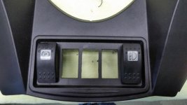
No. You have to remove the front and side tupperware from both sides. Then the cable to the glovebox is an easy disconnect. There are two bolts on each side of the module that is both the glove box and the switch panel. Then disconnect the wire harness plugs from each of the other switches. Now you can take the module to a workbench. You just pop out the blank from the center position, but the hole there is a small round hole. You have to take either a Dremel tool or an Xacto knife and cut out the hole to a rectangle the same size as the others. The Carling switches are a friction fit. If you cut the hole too big, they will not stay in. With all the bodywork off, it's not hard at all to pull your wires through. It is a lot of work, but it's a one time only thing and the rewards make the work worth it.

edit:

Forgot. There IS a hidden plastic rivet that IS a PITA holding the whole module in. It is mounted running from the front of the Spyder to the rear UNDERNEATH the module. In the one photo below, you can see the round hole that the rivet goes in, but keep in mind, in this photo, the module is upside down. Your need long needlenose pliers to get this rivet released and removed.

attachment.php
attachment.php
 

Attachments

  • cutout.jpg
    cutout.jpg
    38 KB · Views: 103
  • switch module.jpg
    switch module.jpg
    40.3 KB · Views: 107
Last edited:
I'd love to know what route you took for the wires from the switch down and out to the main parts of the bike.

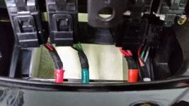
There's only 4 wires coming off the switch. They all come down the left side from the switch panel. The shortest one is the black ground for the internal switch light. I put a ring terminal on that and just attached it to a frame bolt. Didn't have to remove any paint, I metered it out to the battery negative and it was a perfect ground. One of the red positive wires comes down and follows the main wiring harness forward and out through the rubber plug into the frunk where I mounted my garage door opener. The garage door opener ground is the ground from the unused optional power port in the frunk. The positive from the unused power port goes back up to feed the ACC switch the switched power by way of the F6 fuse. The other red positive wire comes down with the others and then goes back along the edge of the fuel tank and comes out of the existing opening at about the middle of the seat. That is where I mounted an aux fuse panel. From there I have power going back up onto the handlebars for my portable satellite radio, and also into the left side bag where I mounted the video recorder for my front and rear cameras. The grand total of all the current pulled from all the devices is way under what the power port is rated for, and each is also separately fused.
 
Back
Top