The Governor
New member
2010, RTS-SM5. The ambient temp sensor primarily supplies important variable information to the ECM for air/fuel ratio mixture, and shows the rider (roughly) the outside air temperature, I felt it has been poorly located from the factory. For those that don't know where it lives, it is located out of any airflow on the right side of the frunk inboard of the right fog light assembly. It is held in place by one bolt, 10mm.
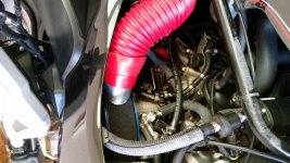
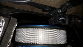
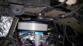
I removed the sensor, unplugged it, and decided to mount it directly above my new air cleaner (THANKS JT!) I installed the new air ducting mod last year to resolve the cooling issues, and thus creating massive amounts of cooling air to now flow into and thru the engine compartment. I will certainly update this post with any and all results from my new mod....
One observation prior to this mod- the static air temp at startup was typically incorrect, and now in a position of high airflow, I'm interested to see how quickly it will correct itself...
Gov
 I've heard of this happening. Thanks for letting us know that it's based in fact! :thumbup: