D
Doc - Riverside
Guest
This is how I installed the Electric Frunk release on my 2014 RT. I found that the wiring harness is still intact but is missing parts. The switches used on the console are Contura Style. One could try to buy the switch from BRP at a cost of $60.00 which has a blue instead of orange light and replace the parking brake switch to have the Frunk release function back in the original location. Going this route you still need the actuator, mounting hardware and connector parts. Next option is to purchase the $100 kit option that moves the switch option to the Fog light position switch. Besides cost I don't like the idea of turning the fog lights off every time I want to open the Frunk. My Fog lights are always on.
The option I went with is to install a Double Pole - Double Throw (momentary on) switch in the center position of the switch console. Rear of switch is to open the Frunk ( original design) and the front of the switch is to operate the Garage door opener.
Here is a picture of the parts needed
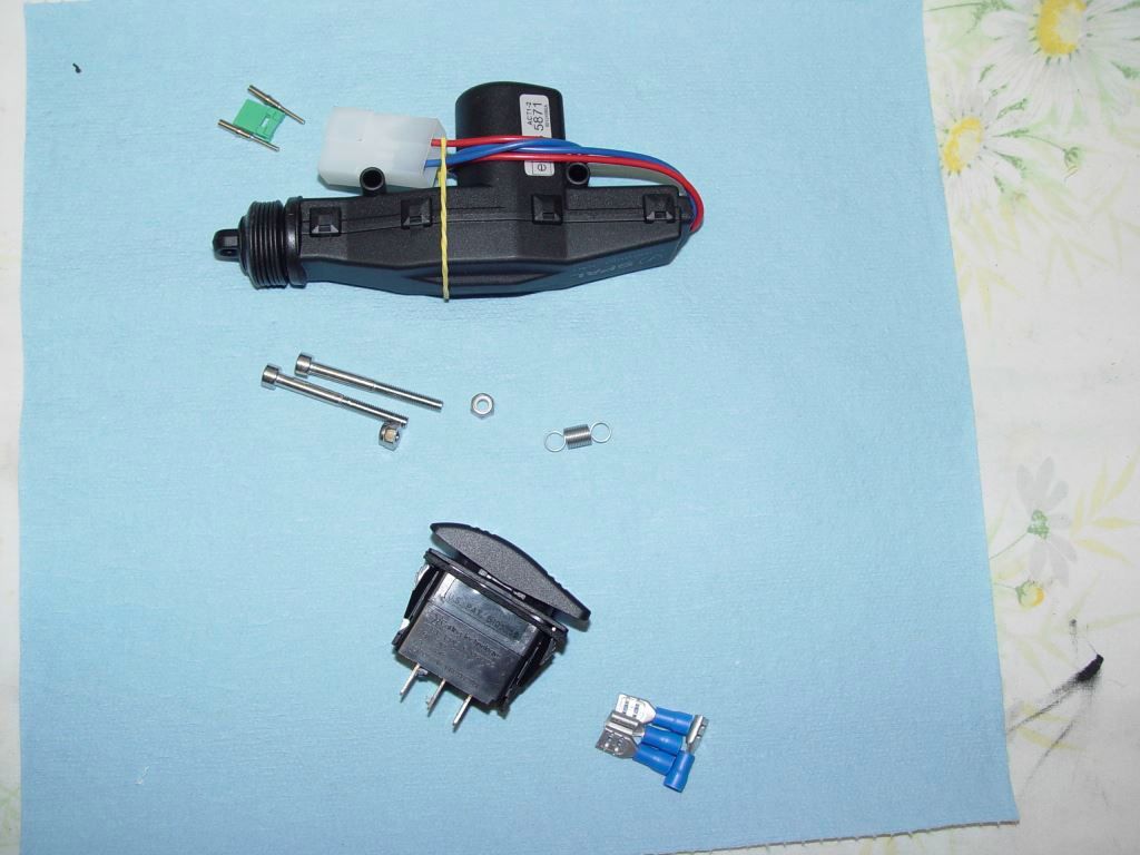
Top left is the two male pins and green wedge block you need for the connector you install on the actuator. The pins are a crimp style but can be soldered.
Pins from http://www.deutschconnector.com/products/deutsch_pins_and_sockets/deutsch_dt_pins_and_sockets/0460-202-16141/
wedge from
http://www.deutschconnector.com/pro...parts/deutsch_dt_2-way_replacement_parts/W2P/
For the Actuator Google " SPAL 37000003 ".
For the Switch Google " Blue Sea Systems Contura 8290 switch "
Spring can be ordered from ( WWW.McMaster.com ) Part number 9065K194
The bolts and lock nuts can be ordered from Bolt Depot
m4 x 40 bolt
https://www.boltdepot.com/Product-Details.aspx?product=6402
m4 lock nut
https://www.boltdepot.com/Product-Details.aspx?product=4793
You will also need 1/4 inch male and female spade lugs, tie wraps and heat shrink.
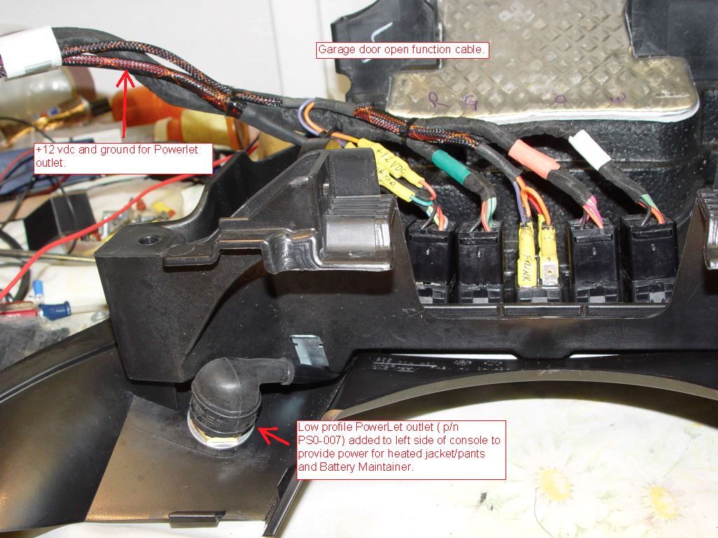
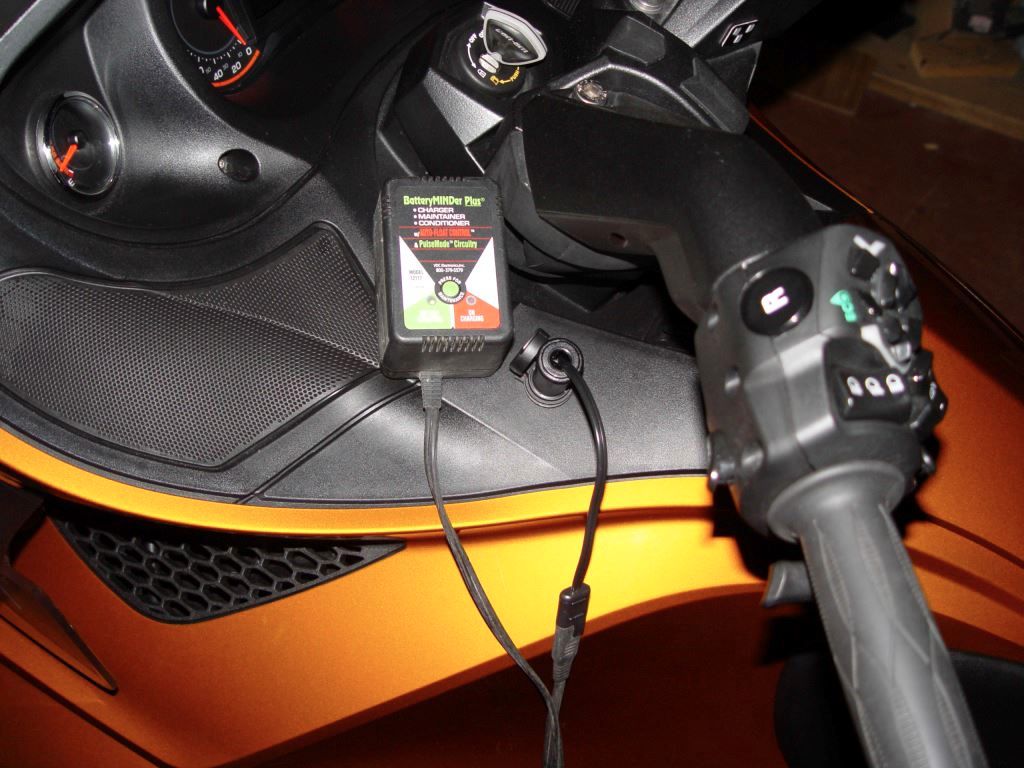
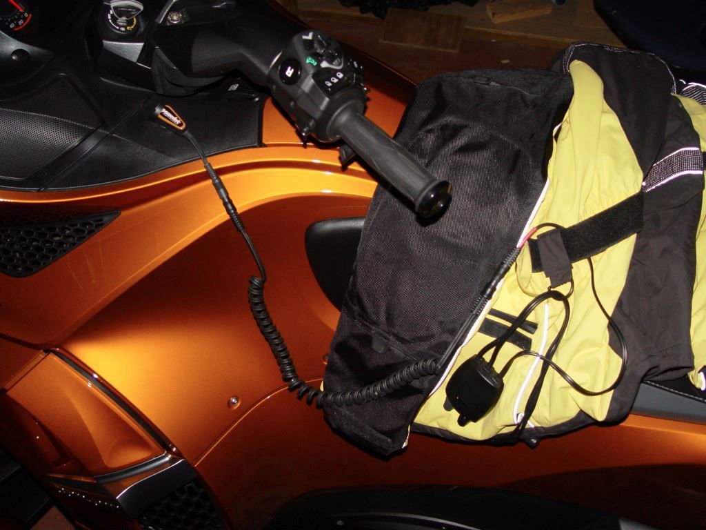
Google " Powerlet PSO-007 " if you want to install +12vdc power on the left side of the glove box for plugging in a battery maintainer of heated cloths.
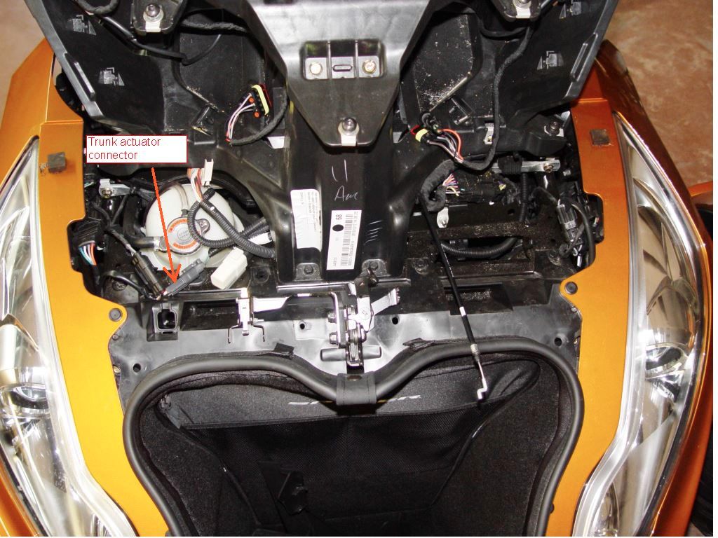
To get started you need to remove both mirror, lower wind deflectors, both upper side panels, Headlight trim and the two triangle pieces of plastic in the frunk. Locate and remove the connector plug as shown. This will be installed on the actuator.
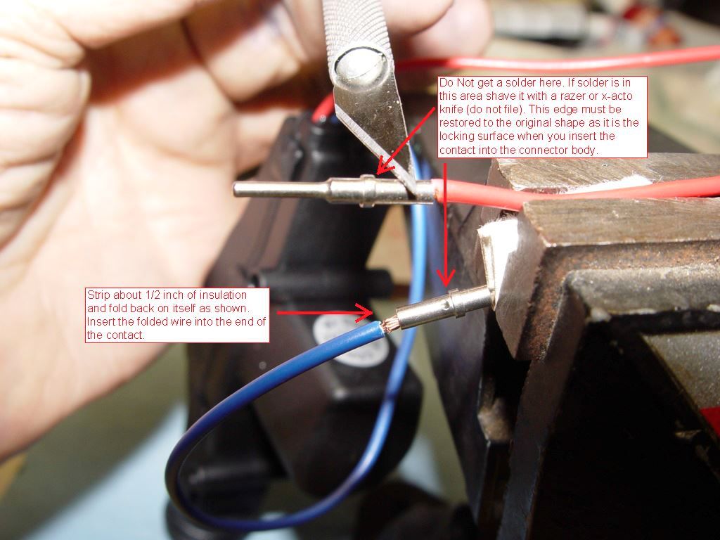
Now we will install the pins on the actuator. Cut the white nylon connector off the actuator and discard. At the plug you removed from the trunk actuator connector remove the two white pins and the reddish rubber gasket. Install the red gasket on the red and blue wire of the actuator. The contacts can be crimped on if you have the $300 crimper or you can solder them on the wire. Do Not try to do the crimp with pliers. It will deform the contact so it won't seat in the connector body. It is critical that you use just enough solder to do the job. The lip shown in the picture must remain as close to original shape as possible for the contact to lock into the connector. When soldering the pin use heavy paper between the pin and the clamping device. This prevents the device from becoming a heat sink while you are trying to solder.
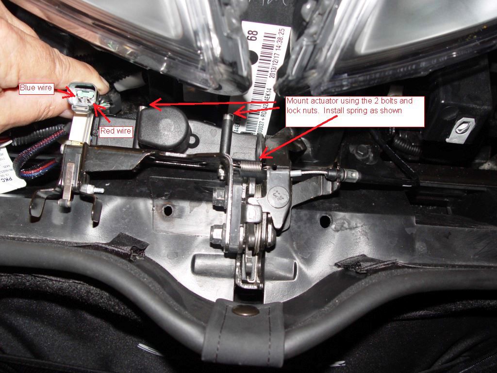
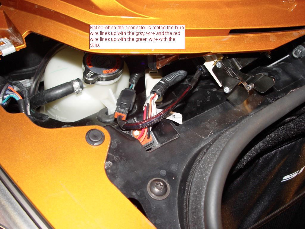
Now you are ready to put the pins into the connector body. Use the below two pictures to ensure the pins are located correctly. The red wire should line up with the green wire when you mate the two connector. With the pins inserted into the connector install the green wedge as shown and firmly seat. Slide the red gasket into the back the back of the connector. Now mount the actuator and spring.
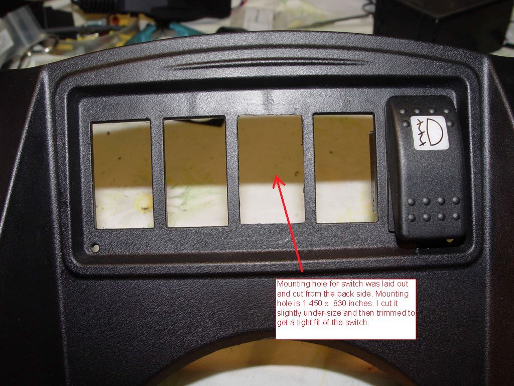
To install the new switch and Powerlet outlet remove the Glove box. Remove plastic rivet's and plastic parts until you get to the switches and harness. Disconnect all the switches and remove the harness. Remove the switches. Mark up the center for the new switch mounting hole and cut out. It is best to be slightly under size on the hole and then carefully open it up to just fit the new switch.
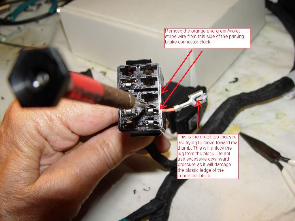
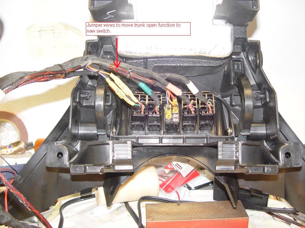
Next step is to remove the two female spade contacts from the switch connector for the parking brake. You want to remove the two wires as shown. Orange is +12vdc switched power and the green/violet goes to the red wire on the actuator.
Reinstall the switches and reconnect the harness to the switches. Mount the Powerlet outlet as shown.
Using the male and female spade lugs, fabricate a new wire harness to connect up the power and actuator signal to the new switch. Cover the new harness connection to the orange and green/violet wire with heat shrink. The orange wire was connected to two center posts of the switch because my garage door opener requires 12vdc to operate. The left center lug of the new switch is the only one that needs the orange wire for the actuator to work. What you use the second option of the switch is your choice. I wired the rear of the switch to open the Frunk.
Powerlet wires also had extra red and black wire added to extend the wire for hookup at the alternator.
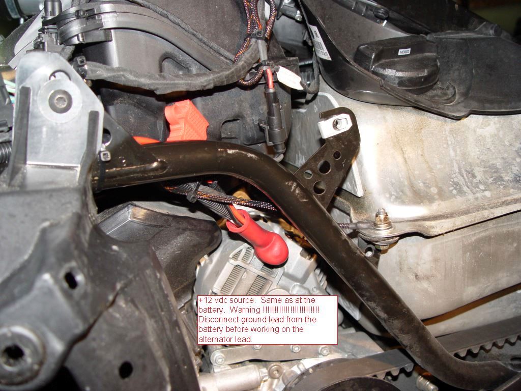
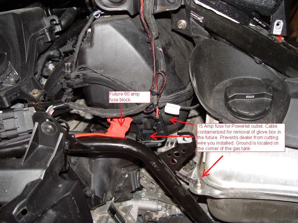
Picture showing how +12vdc is picked up off the alternator post. Warning !!!!!!!!!!!!!! disconnect negative lead on battery prior to working on alternator post. I made up two inline fused connections. One is for a yet to be added fuse block (Red Fuse ) and the black one is for the Powerlet outlet ( fused at 15amps) .
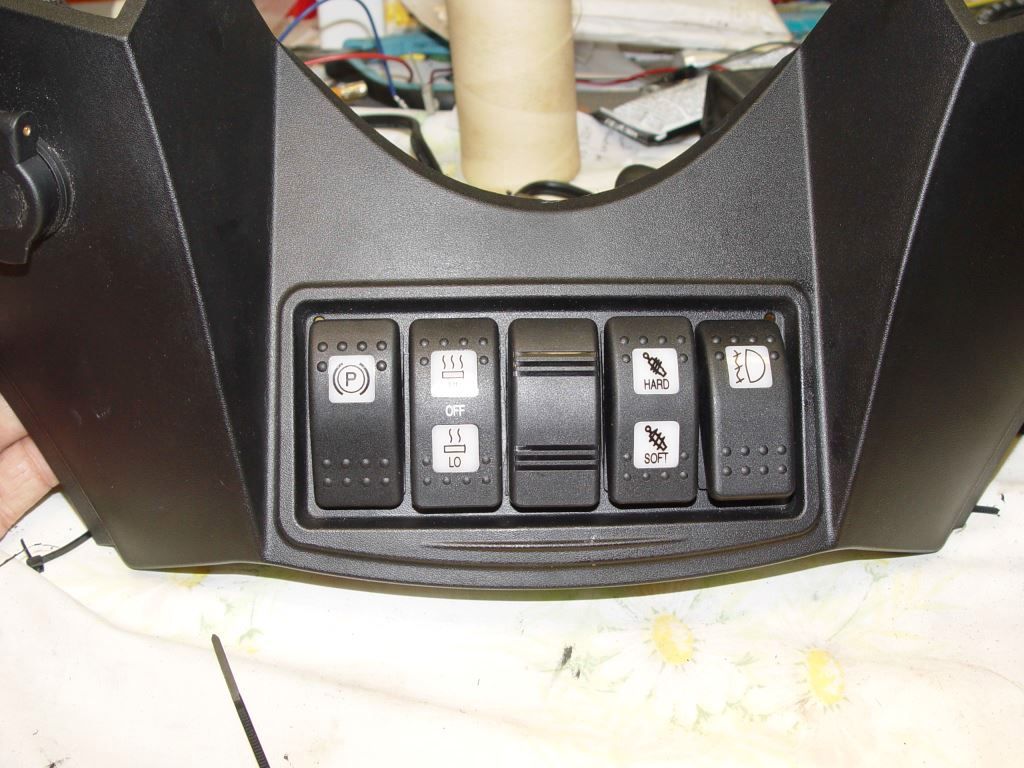
Final product
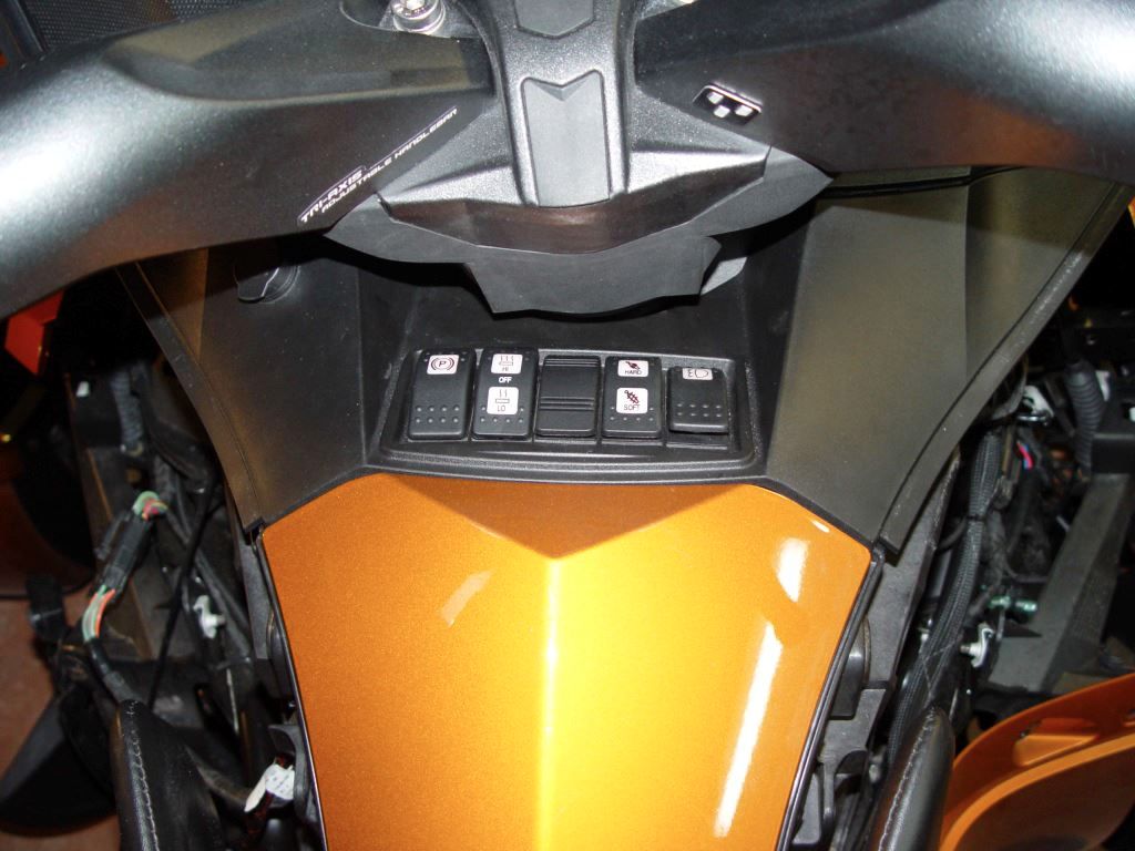
The option I went with is to install a Double Pole - Double Throw (momentary on) switch in the center position of the switch console. Rear of switch is to open the Frunk ( original design) and the front of the switch is to operate the Garage door opener.
Here is a picture of the parts needed

Top left is the two male pins and green wedge block you need for the connector you install on the actuator. The pins are a crimp style but can be soldered.
Pins from http://www.deutschconnector.com/products/deutsch_pins_and_sockets/deutsch_dt_pins_and_sockets/0460-202-16141/
wedge from
http://www.deutschconnector.com/pro...parts/deutsch_dt_2-way_replacement_parts/W2P/
For the Actuator Google " SPAL 37000003 ".
For the Switch Google " Blue Sea Systems Contura 8290 switch "
Spring can be ordered from ( WWW.McMaster.com ) Part number 9065K194
The bolts and lock nuts can be ordered from Bolt Depot
m4 x 40 bolt
https://www.boltdepot.com/Product-Details.aspx?product=6402
m4 lock nut
https://www.boltdepot.com/Product-Details.aspx?product=4793
You will also need 1/4 inch male and female spade lugs, tie wraps and heat shrink.
Google " Powerlet PSO-007 " if you want to install +12vdc power on the left side of the glove box for plugging in a battery maintainer of heated cloths.
To get started you need to remove both mirror, lower wind deflectors, both upper side panels, Headlight trim and the two triangle pieces of plastic in the frunk. Locate and remove the connector plug as shown. This will be installed on the actuator.

Now we will install the pins on the actuator. Cut the white nylon connector off the actuator and discard. At the plug you removed from the trunk actuator connector remove the two white pins and the reddish rubber gasket. Install the red gasket on the red and blue wire of the actuator. The contacts can be crimped on if you have the $300 crimper or you can solder them on the wire. Do Not try to do the crimp with pliers. It will deform the contact so it won't seat in the connector body. It is critical that you use just enough solder to do the job. The lip shown in the picture must remain as close to original shape as possible for the contact to lock into the connector. When soldering the pin use heavy paper between the pin and the clamping device. This prevents the device from becoming a heat sink while you are trying to solder.

Now you are ready to put the pins into the connector body. Use the below two pictures to ensure the pins are located correctly. The red wire should line up with the green wire when you mate the two connector. With the pins inserted into the connector install the green wedge as shown and firmly seat. Slide the red gasket into the back the back of the connector. Now mount the actuator and spring.


To install the new switch and Powerlet outlet remove the Glove box. Remove plastic rivet's and plastic parts until you get to the switches and harness. Disconnect all the switches and remove the harness. Remove the switches. Mark up the center for the new switch mounting hole and cut out. It is best to be slightly under size on the hole and then carefully open it up to just fit the new switch.

Next step is to remove the two female spade contacts from the switch connector for the parking brake. You want to remove the two wires as shown. Orange is +12vdc switched power and the green/violet goes to the red wire on the actuator.

Reinstall the switches and reconnect the harness to the switches. Mount the Powerlet outlet as shown.

Using the male and female spade lugs, fabricate a new wire harness to connect up the power and actuator signal to the new switch. Cover the new harness connection to the orange and green/violet wire with heat shrink. The orange wire was connected to two center posts of the switch because my garage door opener requires 12vdc to operate. The left center lug of the new switch is the only one that needs the orange wire for the actuator to work. What you use the second option of the switch is your choice. I wired the rear of the switch to open the Frunk.

Powerlet wires also had extra red and black wire added to extend the wire for hookup at the alternator.

Picture showing how +12vdc is picked up off the alternator post. Warning !!!!!!!!!!!!!! disconnect negative lead on battery prior to working on alternator post. I made up two inline fused connections. One is for a yet to be added fuse block (Red Fuse ) and the black one is for the Powerlet outlet ( fused at 15amps) .


Final product


")


")