-
There were many reasons for the change of the site software, the biggest was security. The age of the old software also meant no server updates for certain programs. There are many benefits to the new software, one of the biggest is the mobile functionality. Ill fix up some stuff in the coming days, we'll also try to get some of the old addons back or the data imported back into the site like the garage. To create a thread or to reply with a post is basically the same as it was in the prior software. The default style of the site is light colored, but i temporarily added a darker colored style, to change you can find a link at the bottom of the site.
You are using an out of date browser. It may not display this or other websites correctly.
You should upgrade or use an alternative browser.
You should upgrade or use an alternative browser.
Am I right in thinking...
- Thread starter jwulf74
- Start date
billybovine
Active member
...that we collectively determined that the PTT button on the RT's is not hooked into the CAN-BUS? Basically I want to disconnect the wires that are there and use it for something else...
According to the 2013 wiring diagram the PTT button is a CAN device. A lot of the buttons on the left hand handlebar control cluster are internally connected to a board that connects to the CAN-bus.
robmorg
New member
Billy,According to the 2013 wiring diagram the PTT button is a CAN device. A lot of the buttons on the left hand handlebar control cluster are internally connected to a board that connects to the CAN-bus.
Out of curiosity, may I ask where you see this. The over-all schematic at the back of the shop manual does not go into that much detail about how the multi-function control is wired, although most of the functions it controls are represented on the large schematic.
billybovine
Active member
Billy,
Out of curiosity, may I ask where you see this. The over-all schematic at the back of the shop manual does not go into that much detail about how the multi-function control is wired, although most of the functions it controls are represented on the large schematic.
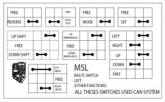
Look at all 3 occurrences of MSL (Multi Switch Left) on the wiring diagram together. There are not enough wires to handle all the functions that it does. Plus 4 lines from the MSR (Multi Switch Right) for cruise control functions that enter the MSL and don't leave. There is a CAN-HI and a CAN-LO wire connected to the MSL and that can only be done through a communication chip. Logically it has to be inside the MSL. The only hardwired functions switches are high/low beam and horn. At the bottom of the wiring diagram, there is a representation of the other switches that use the CAN.
Attachments
WA5VHU
New member
Everything CAN-BUS?
Everything goes through the CAN-BUS. The light from my headlights must first go the the CAN-BUS to verify it is correct before it is allowed to shine down the road.
Sorry, just had to say that. There is one person that was on this board a while back that carefully unsoldered the PTT switch from the wires or flexible circuit board up in the handlebars and soldered their own pair of wires to run to their FTM-10R radio. Worked like a champ for them and the CAN-BUS didn't even know the switch wasn't there any more, except it may have caused all that flooding down there in Texas. There are references and links to that thread but for some reason the thread is not there anymore.
Charles
robmorg
New member
I have followed most all of the circuits on the wiring diagram, but what I have NOT done is physically examined the MSL itself to actually see that all the "wires" (connections) depicted in the diagram are not physically there. Some of these functions could indeed be handled by a chip on a circuit board, so your explanation makes sense. Thanks. :thumbup:Look at all 3 occurrences of MSL (Multi Switch Left) on the wiring diagram together. There are not enough wires to handle all the functions that it does. Plus 4 lines from the MSR (Multi Switch Right) for cruise control functions that enter the MSL and don't leave. There is a CAN-HI and a CAN-LO wire connected to the MSL and that can only be done through a communication chip. Logically it has to be inside the MSL. The only hardwired functions switches are high/low beam and horn. At the bottom of the wiring diagram, there is a representation of the other switches that use the CAN.
That's not to say that what Charles just said above concerning carefully clipping and unsoldering the wires themselves that go directly to the PTT switch and attaching new wires for some other function would not work. Indeed it would, but that would likely be very intricate work, and not for the novice.
Last edited:
billybovine
Active member
I have followed most all of the circuits on the wiring diagram, but what I have NOT done is physically examined the MSL itself to actually see that all the "wires" (connections) depicted in the diagram are not physically there. Some of these functions could indeed be handled by a chip on a circuit board, so your explanation makes sense. Thanks. :thumbup:
That's not to say that what Charles just said above concerning carefully clipping and unsoldering the wires themselves that go directly to the PTT switch and attaching new wires for some other function would not work. Indeed it would, but that would likely be very intricate work, and not for the novice.
I have not seen the innards of the left switches, but because of the wiring diagram some basic assumptions can be made. I agree the OP should be able to take apart the multi switch. Cut the wires or trace on film for the PTT switch for an extremely low current application.
Bob Denman
New member
Everything goes through the CAN-BUS... There is one person that was on this board a while back that carefully unsoldered the PTT switch from the wires or flexible circuit board up in the handlebars and soldered their own pair of wires to run to their FTM-10R radio. Worked like a champ for them and the CAN-BUS didn't even know the switch wasn't there any more, except it may have caused all that flooding down there in Texas.
One of the seven signs of the Apocalypse?? :shocked:
At least it's good to know that it CAN be done... even if it does make it start raining Frogs!
IdahoMtnSpyder
Well-known member
You sure? You're spoofing, right? I just decided that was the case after I wrote all the following!Everything goes through the CAN-BUS. The light from my headlights must first go the the CAN-BUS to verify it is correct before it is allowed to shine down the road.
")
I don't see that on the wiring diagrams. The only can bus association the headlights would have is the fact the ground lines from the hi and low relays is controlled by the ECM which is what activates the headlight relays, and the hi/low switch controls the main headlight relay via can bus. Otherwise the headlight bulbs connect directly to battery power through the relays. The ECM keeps the headlights off while starting to avoid excessive load on the battery.
billy, and others. The section of the service manual that discusses the CAN, Controller Area Network, describes how the left switch cluster connects to the right switch cluster which then is connected to the can bus.
Bob Denman
New member
:shocked: I would be VERY cautious... :shocked:
IdahoMtnSpyder
Well-known member
Wise decision I say. Especially when you consider that if you screwed up the left multi-switch you'd be out about $400 to replace it! :banghead:Thanks everybody. I was thinking of using the PTT for a garage door remote trigger, but since it sounds like it requires minor surgery on the control I don't think I will attempt this one.
billybovine
Active member
Thanks everybody. I was thinking of using the PTT for a garage door remote trigger, but since it sounds like it requires minor surgery on the control I don't think I will attempt this one.
That would be a good use for that unused button if it was easier to tap into.
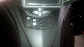
I install a 3 button remote on my ST and I put the buttons here.
Attachments
finless
New member
Roger has a post on here where he in fact took the left grip apart and cut the ribbon cable that goes to the PTT button.
It works trust me!
But again once the can sends it message to the radio, the radio pass this to the CB. There appears to be a pin out that comes from the radio that goes from low to high or high to low when this happens. We should be able to use this to trigger things like the Midland CB.
I will be working on this over the next few weeks.
Bob
robmorg
New member
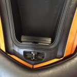
That looks like a good idea. Alternately, you could buy a small remote that would open the garage door. Open it up, and parallel the button with a small wire pair, which could go to a mini-momentary push button you could mount just about anywhere. ...or you could get a "CribClicker" (or a similar module), which would open your garage with the headlight switch. I agree that I wouldn't mess with the PTT switch when there are so many other easier options.I put some velcro on the lower edge of my glove box to hold the garage door opener. It's out of the weather and I only have to open the glove box twice per ride to use it.
Bob Denman
New member
I saved the glovebox foam insulation out of my 2010 (") ), cut a hole in the front panel, and stuffed my garage door opener in there! :thumbup:
), cut a hole in the front panel, and stuffed my garage door opener in there! :thumbup:
), cut a hole in the front panel, and stuffed my garage door opener in there! :thumbup:Similar threads
- Replies
- 2
- Views
- 826
- Replies
- 4
- Views
- 697
- Replies
- 3
- Views
- 533
- Replies
- 11
- Views
- 993