• There were many reasons for the change of the site software, the biggest was security. The age of the old software also meant no server updates for certain programs. There are many benefits to the new software, one of the biggest is the mobile functionality. Ill fix up some stuff in the coming days, we'll also try to get some of the old addons back or the data imported back into the site like the garage. To create a thread or to reply with a post is basically the same as it was in the prior software. The default style of the site is light colored, but i temporarily added a darker colored style, to change you can find a link at the bottom of the site.

Adding USB ports to 2024 Spyder F3T - anyone tell me what these wires are for?

Judy24

New member
Since the 2024 F3T doesn’t have the customer accessory wires, I was wondering if I could use the plugs beside the ignition to install a USB port. There’s 4 wires: yellow/blue, black, orange/red, black. Could someone tell me what the orange/red is for? I’m assuming the black are neutral and the yellow/blue is the positive. Any advice would be greatly appreciated. 😊

IMG_3342.jpeg
 
What do they connect or dead end to? Turn the key on and see which have power and how much by probing the connector. Should get you started if you don't have a service manual.
 
Spyder Extras sells a docking station for F3s that has USB ports on it.


The install instructions include where to tap into the bikes wires for power.

 
Since the 2024 F3T doesn’t have the customer accessory wires, I was wondering if I could use the plugs beside the ignition to install a USB port. There’s 4 wires: yellow/blue, black, orange/red, black. Could someone tell me what the orange/red is for? I’m assuming the black are neutral and the yellow/blue is the positive. Any advice would be greatly appreciated. 😊
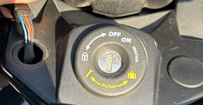
View attachment 249960
Those are probably the factory wiring for the heated grips which come on the Limited.
 
Those are the wires/plugs for the Heated Grips (left side) and for Fog Lights (right side) on North American models. The power wire won't become energized until after the engine is started due to the load shedding relay system used; more power available to crank the engine.

Start the engine, use a multimeter or 12 vDC circuit detector light to find the energized wire. Bear in mind that the CAN-Bus system doesn't appreciate unexpected high current draw accessories. A USB 3.0 port will likely draw about 24 watts, or 2 amps. Multiple ports will draw more current. I would be cautious about putting too much load on one circuit. If you need more, tap into the right side (Fog Light) circuit.
 
PowerSports Diagnostics just uploaded the 2023 F3 manual with electrical schematic. BRP has changed to a relay to drive the heated grips vs a direct switch. #1 and #3 wires are, indeed, grounds. The #2 wire (OR/RD) is for the annunciator light and is common to many of the dash lights on the bike; tapping into that wire could cause CAN-Bus issues for power draw. The power wire is in the #4 position that drives thru the relay, RY5L. If you tap into that wire, at the console switch, the circuit will be completed and the heated grips will be on all the time.

It is a pain, but the best way would be to go direct to battery. Put an in-line power relay to come on with the key, and you'll have power for lots of aftermarket goodies plus the USB ports.
 
Last edited:

^^ Tips for finding switched wires to tap into.

Sarah
 
In the very back of almost all Shop Manuals (not the Owner's Manual) there should be a couple pages of electrical schematics. The wires are all colour coded and labelled somewhere along them. You have to trace them to see where they go and where they come from. The schematics are supposed to be specific to the model and the year. This is not just for Can Am, it should work for any vehicle, if you have a good shop manual for it.

disclaimer - Can Am Shop Manuals are difficult to even find until the model is several years old, and even then, they're not always dependable.
 
disclaimer - Can Am Shop Manuals are difficult to even find until the model is several years old, and even then, they're not always dependable.
I stumbled across this a while back. They don't have the 2025 manual yet, but it lists 2008 thru 2024:

Can-Am Ryker & Spyder Series Shop Repair & Maintenance Manuals


Adobe Acrobat format for US $24.50
 
I stumbled across something on my 2019 F3-S a while back too. I was looking for a plug and play trailer light hook up. Talking to a Can Am Custom accessories place in Canada on the phone. They had a plug and play that would work on the F3-S, but the F3-S didn't have the plugs on the wire. It was the same wiring harness used on the touring and cruiser machines, but they just put a shrink fit connection on the hot wire under the seat, which would have been for extra lights on saddlebags or maybe a usb terminal inside the trunk. The guy I was talking to was very familiar with all the different models and knew where all the dead-ended wires in the harness were located and what they were originally for. The place didn't like to sell something advertised as plug and play that you would have to locate a hidden wire, and solder into to make the plug and play work. Told him I didn't mind, just tell me the colour code on the hot wire and I will be happy to do the hook up myself. They sent me one, every other wire on the trailer adaptor (small box fits under seat) plugged right in the capped off harness I found tucked under the seat. Located the hot wire and put a plug on it to match the one for hot coming out of the plug and play unit. Plugged the trailer I had just built in. All the lights, blinkers, the side marker lights I put on the sides of the trailer worked perfect first time plugged in. All the trailer lights, brake, turn signals, and markers worked exactly as they should using only a flat 4 connector to hook the trailer harness to the plug from the scooter.

There are wires on some of the sport cruiser machines in the harness not being used, capped off with shrink fit and hidden. The wires go to accessories usually found on the touring machines. I suppose it is less expensive and fewer parts to have on hand, to use the same harness for several models and just cap off the unused wiring, before they use it on the models that do not normally have that accessory installed, or sell it as an upgrade.
 
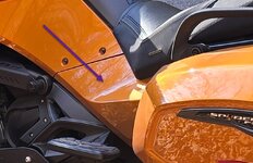
I have a 24 F3 Limited Special and there is an accessory plug located under this panel on the left side. It is a 2 pin connector that is located on the top of the frame tube and has a plug on the end of it that you can remove. It is a circuit that works when the key is on. I don't know if it is on other models, but it is on mine.

Accessory Pin Location.jpg
 
Back
Top