mcalva
Member
Hi.
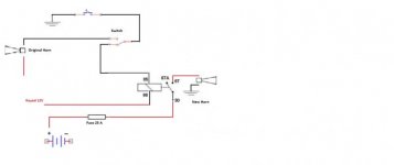
I would like to mount an additional aa oo gaa horn as "fun" on my f3, respecting the original with a switch to select one or the other.
The positive should come out from the electrical socket for user accessories and the negative would be the one that comes out of the
horn's push button.
I would like to do it as sure as possible and install a relay to not to damage the horn button.
Any suggestion? I saw an outline where
it was explained, but now I can't find it, now.
Thank you in advance