• There were many reasons for the change of the site software, the biggest was security. The age of the old software also meant no server updates for certain programs. There are many benefits to the new software, one of the biggest is the mobile functionality. Ill fix up some stuff in the coming days, we'll also try to get some of the old addons back or the data imported back into the site like the garage. To create a thread or to reply with a post is basically the same as it was in the prior software. The default style of the site is light colored, but i temporarily added a darker colored style, to change you can find a link at the bottom of the site.

A little Can Bus tutorial

IdahoMtnSpyder

Active member
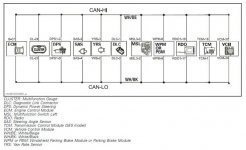
There has been some misunderstanding here about what the Can Bus is and isn't on our Spyders, and what it affects. CAN refers to Controller Area Network. Can Bus generally refers to a communication protocol among various components on the Spyder. Here is a overview of the network.

attachment.php


Brake lights, tail lights, and headlights all are powered by 12 volt lines controlled by switches and relays. Turn signals are the only lights tied into the Can Bus, and then not directly. TS are operated by the cluster which communicates with the left side multi-switch via the Can Bus network.

Looking at the diagram you can see that all the various controllers communicate over the network, the engine, the stability system, the power steering, the radio, the left switch, and so on. But they do not all communicate with every other one. The engine doesn't talk to the MSL or the radio. But the MSL talks to the radio and to the cluster. The VSS talks to the ECM but not the radio. Nobody on the network talks to the brake light, but the brake light switch is one of the inputs to the ECM, which has as one of its functions cruise control. The engine and transmission talk to each other, and the MSL talks to the SE transmission module, which is how the shifting is controlled.

So you see, there is a lot of communication going on among the various modules, but only to the modules. The modules then control everything else, some by controlling power directly such as the turn signals, and some by controlling relays like the load shedding relay which is what controls power to the headlights, grip heaters, etc.

This is probably somewhat rambling and confusing to some, but hopefully it'll help us all understand the role of the Can Bus a little bit better. If I didn't make something clear enough ask away.
 

Attachments

  • CanBus network.jpg
    CanBus network.jpg
    48.1 KB · Views: 1,067
WOW... "Shove me in the shallow water before I get to deep" thanks that's a lot of information:thumbup: jtpollock
 
Bus

Can Bus? I always thought that was the bus to Canada.:yes::yes::yes:

Actually, that was a very nice explaination. Thank you.
 
Even though it went over my head quicker than an f-18 with it's afterburners lit :shocked:; thanks for posting this information... :thumbup:
 
If you understand LAN protocols, each device has an address.
In a packet of data sent from anything it has a address in the header for the destination component.
It's not that the VSS doesn't talk to the radio, the radio actually does see the packet the VSS sent but it just ignores it as the packet is not addresses to it.

Bob
 
Sounds like when I was married
Except nobody talked to each other :yikes:
Can you say Limp Mode :roflblack:
 
Can bus

Thanks for the detailed explanation.
The Canbus has always been very intimidating for farkeling. :shocked:
So my question. Where is a safe place to tap for a switched power signal for a relay connection at an auxiliary fuse block?
Right now I'm using the signal from the switched power from my heated grip control. If my understanding is correct, the heated grip connection is not a module so I'm not messing with the load on the Canbus.

The HI and LOW CAN lines are on white wires with either a black or beige tracer color. They should never be tapped into for any reason.

Circuits that are monitored for current draw like turn signals lights, hazard warning lights and brake lights. Caution must be taken and avoided when practical.

Any other circuit are far games except you must not exceed the current load as protected by the fuse of course.

Any devices added to your Spyder could cause electrical noise and that noise could leak over to the CAN BUS even if it is not connected directly to it. That could interfere with the communication between modules. Make sure everything you add is easy to disconnect in case troubleshooting is required.
 
If you understand LAN protocols, each device has an address.
In a packet of data sent from anything it has a address in the header for the destination component.
It's not that the VSS doesn't talk to the radio, the radio actually does see the packet the VSS sent but it just ignores it as the packet is not addresses to it.

Bob
Good clarification. Thanks.
 
The HI and LOW CAN lines are on white wires with either a black or beige tracer color. They should never be tapped into for any reason.

Circuits that are monitored for current draw like turn signals lights, hazard warning lights and brake lights. Caution must be taken and avoided when practical.

Any other circuit are far games except you must not exceed the current load as protected by the fuse of course.
I don't find anything in the wiring diagram or the service manual that indicates the brake light current draw is monitored. The turn and hazard yes, since they are fed directly from the cluster.
Any devices added to your Spyder could cause electrical noise and that noise could leak over to the CAN BUS even if it is not connected directly to it. That could interfere with the communication between modules. Make sure everything you add is easy to disconnect in case troubleshooting is required.
Good guidance. The interference with Can Bus signals is what happened when some folks added HID aftermarket headlights. That also was what happened with the early 2014s with the older CBs. I don't know what the installation configuration actually was that caused the problem but as soon the PTT was pushed the transmit signal mucked up the Can Bus signals and caused a Limp Home error.
 
PTT is on the can-bus. Not the button itself but the button hooks to the CAN controller in the left grip.

So I doubt the issue with the CB was the PTT itself having a problem on the bus. The CB would recieve the PTT data packet and whatever the CB did messed up the buss.

I believe the issue as I recall came down to a design problem in the CB itself and required a new CB? But going by old memory here so not 100% sure.

Bob
 
Bob,
Would it be possible to physically disconnect the PTT button from the can-bus system, and put it to use as, say, a remote garage door opener button?
 
Bob,
Would it be possible to physically disconnect the PTT button from the can-bus system, and put it to use as, say, a remote garage door opener button?

Yes... Roger did it and someone else did it.
The PTT button is on a small ribbon cable. You snip this cable just after the button which goes to the can-buss controller in the grip. Now you can solder anything to the button you want.

It not a hard job but some people are not comfortable taking the grip apart nor cutting the cable as once you cut the cable you will not easily be able to put it back to stock.

I was going to come up with something here to do just that so people could use the PTT button but figured not too many people will take the grip apart so I don't think it would be a valuable project. I may revisit that depending on how my PTT converter works when I get back to it this spring.

Bob
 
I don't find anything in the wiring diagram or the service manual that indicates the brake light current draw is monitored. The turn and hazard yes, since they are fed directly from the cluster.

I was wrong on that one and should have known better because I looked that one up before.

Thanks for pointing that out.
 
Yes... Roger did it and someone else did it.
The PTT button is on a small ribbon cable. You snip this cable just after the button which goes to the can-buss controller in the grip. Now you can solder anything to the button you want.
Thanks! :thumbup:
I didn't know if the system would get cranky, if you simply cut the wires.... :shocked:
 
A Practical Question

IdahoMtnSpyder,

Thanks much with this handy tutorial on the Can-Bus. :thumbup:. It is really helpful to know more about what it does. But your original post does bring to mind a practical question that I've been wondering about for some time.

There has been much discussion on this forum about the need for using a relay when replacing the OEM horn with a more current-hungry airhorn. I installed a relay after looking at the electrical diagram for my RT and noticing that the horn was on the same fuse as the load shedding relay. Although the horn is before the load shedding relay in the circuit, the load shedding relay distributes power to other high current devices such as the fog lights, the heated hand grips, the passenger heated grips, and the automatic suspension system on the RT Limited.

So the question is... Because all of this comes off the same fuse in the fuse block , wouldn't it indeed be wise and prudent to install a relay on an air horn , rather than connect it directly to the horn button like the OEM horn is connected?
 
Last edited:
Sorry... I didn't mean to kill the thread with the above post. :sour:

I really was hoping for a logical answer from someone who really understands the Spyder electrical system.
 
Last edited:
Sorry... I didn't mean to kill the thread with the above post. :sour:

I really was hoping for a logical answer from someone who really understands the Spyder electrical system.

For others reading this replacing the horn for another one has nothing to do with the CAN BUS.

Yes there is a lot of stuff on that circuit. Sure it's a good idea to use a relay. Also how rugged is the horn switch to handle the extra current? :dontknow: But on the practical side a lot of people seem to have connected their horn without any ill effects. Any problems should have showed up by now.
 
Back
Top