• There were many reasons for the change of the site software, the biggest was security. The age of the old software also meant no server updates for certain programs. There are many benefits to the new software, one of the biggest is the mobile functionality. Ill fix up some stuff in the coming days, we'll also try to get some of the old addons back or the data imported back into the site like the garage. To create a thread or to reply with a post is basically the same as it was in the prior software. The default style of the site is light colored, but i temporarily added a darker colored style, to change you can find a link at the bottom of the site.

USES FOR THE CB PTT BUTTON

tmcquain

New member
Just curious, but has anyone found any use for this button other than for a CB. I will never use a CB. So I was thinking it would be good for a garage door opener. Don't know how to do it, wire it, or even if it's possible.
But just thought it might be a good idea.


Any Ideas ??
 
On previous bikes, I've run wires from a garage door opener to waterproof buttons I've installed. Now I use an app on my phone.

If you try to wire using the PTT switch, you'll have to CAREFULLY solder 2 wires to the small patterned connectors on the garage door opener circuit board. Very little copper, lots of parts that can be damaged by too much heat. Conceptually it's very easy to do.

If you look at the installation instructions for the CB module, it looks like the connector might be under the glovebox, but that's just a guess.

http://instructions.brp.com/content...ommunication System&rel_part_number=219400611
 
Just curious, but has anyone found any use for this button other than for a CB. I will never use a CB. So I was thinking it would be good for a garage door opener. Don't know how to do it, wire it, or even if it's possible.
But just thought it might be a good idea.


Any Ideas ??
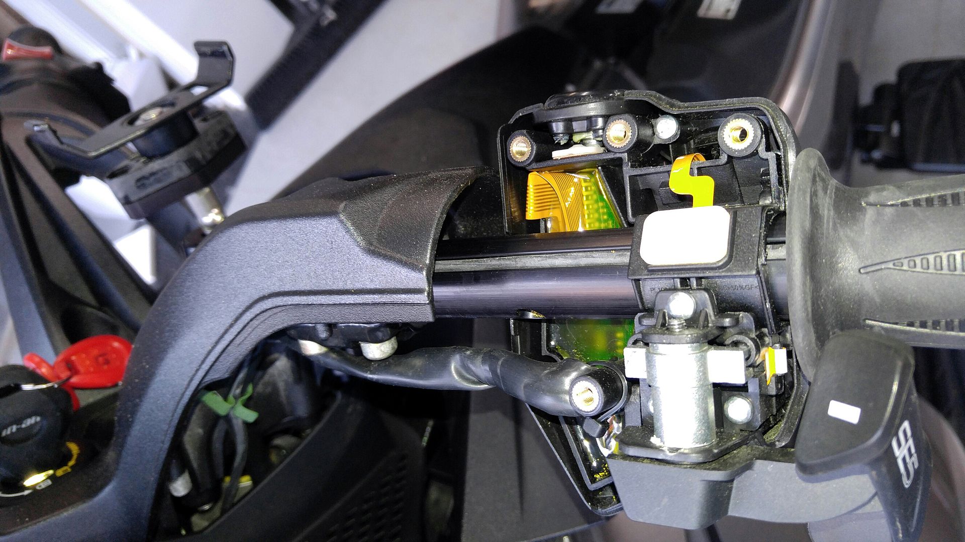
Not practical. The PTT does not connect directly to any wires on the bike. The PTT button activates a contact on a printed circuit board. The circuit board is a CANBUS processor and sends a digital signal to the audio unit when you press the PTT button. If you want to do microsurgery on the circuit board you can tap into to it to connect to the switched traces on the PCB and then make use of the PTT. But if your left switch module ever craps out during the warranty period you'll most likely be out $400 since you mucked with the internals of it.
 
:D I bought the Limited; thinking that it had that...
Now I find out that it's only part of the Un-limited package... :banghead:
 
The PTT button connects to the left grip controller which is then connected to the CAN buss.
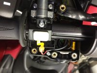
You can in fact disconnect it. It is not on a circuit board.
It has a small ribbon cable attached to it that then runs to the circuit board.
You can cut this ribbon cable and carefully solder wires to it for what you need.

I did not take this picture but this is from someone that did exactly that.


Bob

attachment.php
 

Attachments

  • IMG_0115.jpg
    IMG_0115.jpg
    59.2 KB · Views: 596
The PTT button connects to the left grip controller which is then connected to the CAN buss.
You can in fact disconnect it. It is not on a circuit board.
It has a small ribbon cable attached to it that then runs to the circuit board.
You can cut this ribbon cable and carefully solder wires to it for what you need.

I did not take this picture but this is from someone that did exactly that.


Bob

]
I stand corrected.

Sent from my SM-T350 using Tapatalk
 
The PTT button connects to the left grip controller which is then connected to the CAN buss.
You can in fact disconnect it. It is not on a circuit board.
It has a small ribbon cable attached to it that then runs to the circuit board.
You can cut this ribbon cable and carefully solder wires to it for what you need.

I did not take this picture but this is from someone that did exactly that.


Bob

attachment.php

I wondered what that button was for.

I have it on my wife's ST-S.

Heated%20Grips%206.jpg
 
My project this weekend is to swap the PTT and HORN buttons. I am constantly hitting the horn button in the stock location and cant find it when I do need it. If I put it where the PTT button is, I will have no trouble finding it. Hoping its a straight forward swap.
Most likely not. At least you shouldn't try to swap the functions of each to the other button. The horn button handles up to 10 amps or so. The PTT button handles milliamps at best. Running the horn circuit through the PTT button will undoubtedly burn up the PTT button contacts. Swapping the physical buttons may be a possibility but it would most likely require a lot of physical alteration of the switch assembly.
 
Most likely not. At least you shouldn't try to swap the functions of each to the other button. The horn button handles up to 10 amps or so. The PTT button handles milliamps at best. Running the horn circuit through the PTT button will undoubtedly burn up the PTT button contacts. Swapping the physical buttons may be a possibility but it would most likely require a lot of physical alteration of the switch assembly.
I'm certaily not an auto electrician, but i would think that if the PTT button only activated a relay the difference in amperage should not be a concern, or am i being to simplistic.
 
I'm certaily not an auto electrician, but i would think that if the PTT button only activated a relay the difference in amperage should not be a concern, or am i being to simplistic.
Just make sure the relay has a low pull-in current load. Even then it might be a bit high for the PTT since all it does is close a circuit on a printed circuit board. You could try it and see what happens.
 
I studied the wiring diagram but the PTT circuit is not on it. I was hoping to just swap the switch locations, but that might not be possible. I will keep working on it. If I figure out a way, I will let you know. Why cant they make it a simple switch.
It's not on the wiring diagram since it does not connect to anything on the wiring diagram. It's in the table below the wiring diagram for all the switch functions of the left multi-switch that are part of the CANbus processor. All the controls of the radio are CANbus signals.
 
It is easy enough to check. Look at the switch. If it is connected by the printed flexible ribbon, it is carrying only a signal voltage.

Heated%20Grips%206.jpg
 
you seem to know about this stuff. I just got a sena 50 r thinking on getting the cb radio adapter. I want to hook up my cb on the bike to it. can it be done
 
Back
Top