• There were many reasons for the change of the site software, the biggest was security. The age of the old software also meant no server updates for certain programs. There are many benefits to the new software, one of the biggest is the mobile functionality. Ill fix up some stuff in the coming days, we'll also try to get some of the old addons back or the data imported back into the site like the garage. To create a thread or to reply with a post is basically the same as it was in the prior software. The default style of the site is light colored, but i temporarily added a darker colored style, to change you can find a link at the bottom of the site.

Unused OEM connectors - Anyone know what these connectors are used for?

broderp

New member
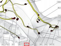
During the install of my accessories and LED's I came across a few connectors that are unused. I was wondering what, if anything, these are used for? Specifically, the one labeled "GPS"? I assume they are used on a different model, but to me it seems like a "free" power outlet that I can utilize.

Anyone know if this is used for anything on any F3 model?

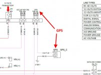
GPS2 - Seems to be tied to the F4R: 5A Fuse. 12V and ground.
 

Attachments

  • GPS2.jpg
    GPS2.jpg
    69.4 KB · Views: 59
  • GPS2_2.jpg
    GPS2_2.jpg
    51.5 KB · Views: 60
Last edited by a moderator:
Yep, as you wrote, that's 'a "free" power outlet', I think it's under the left tupperware, plugged into a holder/keeper to keep it dry and clean when not in use.
 
Last edited by a moderator:
Yep, as you wrote, that's 'a "free" power outlet', I think it's under the left tupperware, plugged into a holder/keeper to keep it dry and clean when not in use.

I finished looking through the electrical diagrams and cannot find where it is used on any model; and on the F3, it is definitely not being used so... I have a free power 5A outlet. :2thumbs:

Thanks for confirming.
 
Last edited by a moderator:
There used to be (as on 2019 F3) a customer power outlet under the left access panel side of the tank. The one on mine was described in the service manual with power recommendations and it was shown on the wiring diaghram for that area. The wiring for it was tucked up under the harness, secured there, and had an inert cover on it.

I used the one on mine to power a USB charger inside the tank bag.
 
There used to be (as on 2019 F3) a customer power outlet under the left access panel side of the tank. The one on mine was described in the service manual with power recommendations and it was shown on the wiring diagram for that area. The wiring for it was tucked up under the harness, secured there, and had an inert cover on it.

I used the one on mine to power a USB charger inside the tank bag.


There still are 3 "Customer Accessory Circuits" as you describe. In the frunk (lower right side); In the left side panel; and in the tail under the passenger seat. These three circuits are all switched (only active when the engine is running and share the same 10A fuse)

There is also another connector (with a protective cover) names "SIG" on the diagram (but "LED1" on the harness chart) near the lower left side of the frunk that is used for the OEM Signature light. It's tied up to a harness and hidden on the outside of the frunk. You need to remove the wire tie and pull it inside the frunk to use. It has power when you turn the key on and your marker and taillights go on.

I was interested in the GPS2 connector, as it is tied to a separate 5A fuse - potentially adding the ability to add an additional 5A of capacity for more accessories; or to be used instead of the Accessory Circuit connectors for easier access and a cleaner install. I will need to see when it is 'on' and how I can utilize this in my project.

:cheers:
 
Last edited by a moderator:
A quick update for anyone reading this in the future...the GPS2 connector has 12vdc when the key is turned to the ON position and the motor not running. When you turn the key to the OFF position power is maintained for several seconds. I have not mapped the Spyder F3-S electrical circuit yet (future project) but I assume that the voltage when on stays on when the motor is running. So if you need a circuit that requires this type of control and can carry up to 5A of current (4A actual working amps with a 20% safety margin) then this will work.
 
Back
Top