• There were many reasons for the change of the site software, the biggest was security. The age of the old software also meant no server updates for certain programs. There are many benefits to the new software, one of the biggest is the mobile functionality. Ill fix up some stuff in the coming days, we'll also try to get some of the old addons back or the data imported back into the site like the garage. To create a thread or to reply with a post is basically the same as it was in the prior software. The default style of the site is light colored, but i temporarily added a darker colored style, to change you can find a link at the bottom of the site.

Nothing spectacular just making it mine.

pitzerwm

New member
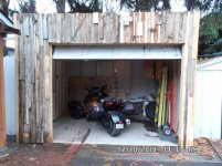
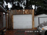
I bought it used a month or so ago and while its been crappy weather, I did get enough riding in to pass the state driving test.

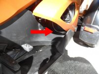
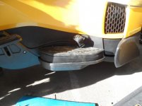
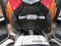
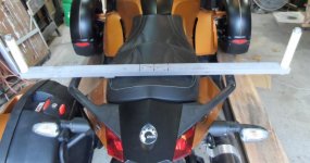
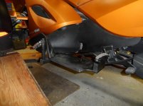
I added the BajaRon's anti sway bar and the links, by taking off the frunk, a piece of cake. These are the videos that helped most. http://www.spyderlovers.com/forums/...-Anti-Sway-Bar-install&highlight=BajaRon+Sway


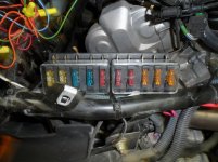
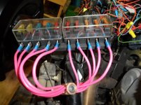
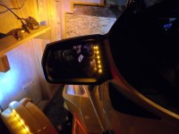
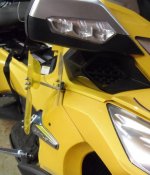
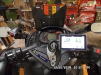
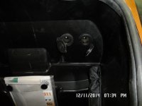
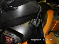
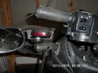
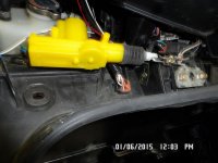
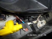
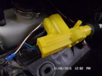
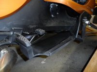
I added 3 power plugs, 2 in the frunk and one on the side. Needed a radar det. so used a Rom X-grip and another one for the GPS or phone. I wired them hot with a switch on the dash

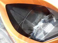
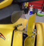
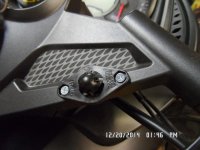
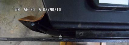
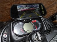
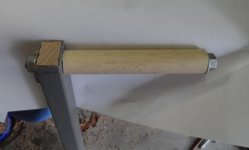
The blue screwdriver on the handlebar is my answer to get the cluster out without removing the windshield.

Added speakers to my helmet that connect to my bluetooth on the phone or the GPS.


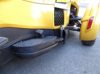
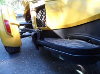
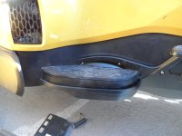
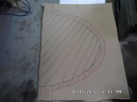
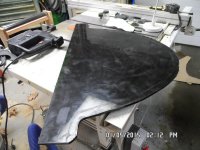
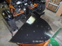
Waiting for an actuator to electrify the frunk. And waiting for the LEDs to be seen easier. Ordered the HDPE stuff to make a bump plate, will post pixs if that works out.
 

Attachments

  • SAM_0656.jpg
    SAM_0656.jpg
    48.1 KB · Views: 963
  • SAM_0659.jpg
    SAM_0659.jpg
    69.1 KB · Views: 1,016
  • SAM_0638.jpg
    SAM_0638.jpg
    91 KB · Views: 806
  • SAM_0639.jpg
    SAM_0639.jpg
    48.3 KB · Views: 790
  • SAM_0646.jpg
    SAM_0646.jpg
    58.2 KB · Views: 898
Last edited:
Build a garage for it as no room in the regular garage. Due to limited space, just enough to park it in, will work on it in the other garage. Installed the opener behind the cluster and a push button switch on the dash.
 

Attachments

  • gar2.jpg
    gar2.jpg
    77.8 KB · Views: 574
  • gar3.jpg
    gar3.jpg
    71.4 KB · Views: 411
Build a garage for it as no room in the regular garage. Due to limited space, just enough to park it in, will work on it in the other garage. Installed the opener behind the cluster and a push button switch on the dash.

You have been very busy adding some nice accessories. Cool siding on your new garage. :thumbup:
 
You have been very busy adding some nice accessories. Cool siding on your new garage. :thumbup:

Thanks, I saw something like it and I tried it out in my living room. There was no way that I would try that small pieces on the garage, or maybe ever again. It's like putting a puzzle together without the picture. The middle "art work" is a screen that splits in half to expose the TV.
 

Attachments

  • Untitled-8.jpg
    Untitled-8.jpg
    29 KB · Views: 410
DIY BumpSkid and a frunk electric actuator

The weather finally got above freezing and I got my supplies. Being frugal/cheap/whatever, I was sold by other's post about the value of the BumpSkid. Not wanting to spend $200, I tracked down the HDPE needed, figuring "how hard could it be". Well, I'm glad that I only needed one. You can see the pixs below of the process. Not having any CNC unit, just normal tools, it didn't come out a slick as Spyderpops'.

I didn't have an easy way to make the forward brackets so I decided to epoxy a piece of wood in the front and then just screw the front down to the wood. I just finished it and don't plan on running into anything to test that the epoxy will hold the wood in place.

I read in another post that the back of the bumpskid didn't lay up to the bottom of the tupperware. On a 2011 RSS the bracket that holds the original plate is to "tall" for it to eliminate the gap. If you removed the old bracket, and screwed it into bottom of the frunk, you would need to have it stop in front of the anti-sway bar. I also decided not to have the back of the bumpskid to flare out. I did use a round over router bit on the perimeter.
 

Attachments

  • bump8.jpg
    bump8.jpg
    36.6 KB · Views: 311
  • bump6.jpg
    bump6.jpg
    63.5 KB · Views: 351
  • bump4.jpg
    bump4.jpg
    53.8 KB · Views: 379
  • bump2.jpg
    bump2.jpg
    61.8 KB · Views: 377
  • bump1.jpg
    bump1.jpg
    21.9 KB · Views: 352
2011 RSS Frunk actuator

I think that any door lock actuator would work, although JIm used a Spal actuator and it might be better. The frunk locking mech. is elevated and do you need to elevate your actuator. Somehow during this process the key no longer unlocks it. I also added a wire from the mech. routed to the "check oil" panel, just in case the actuator quits working.

Electrically I wired it thru the left turn signal power before the push button gets it's power.
 

Attachments

  • act1.jpg
    act1.jpg
    50.7 KB · Views: 269
  • act2.jpg
    act2.jpg
    66.1 KB · Views: 198
  • act3.jpg
    act3.jpg
    37.1 KB · Views: 193
Backup Camera

Reading where others had done this, I decided that was a good idea. Being an old fart, I really can't turn around and look behind me that well.

I picked up a Pyle PLCM7200 at Walmart and I see them on Amazon even cheaper. Having the bigger is better mentality, I got the one (monitor) that you clip on your rear view mirror in the car. As you can see by the pix it is too big for the bike. It is designed to mount the camera on one's licence plate mount. Looking this over, there were issues, one, it covered the year/month stickers and there is the licence plate light that misses with the picture. So I placed it under the seat. I did find that the open lens on the bottom of the brake lights also messed with the picture at night. So you can see that I painted the bottom of the lens. The quality at night was good, and you can see by the pix that daytime quality is great. For some reason you don't need to hookup the "backup light" (green wire). That puts a 12V+ on it. I ran it thru a off/on switch, so I can run it all of the time if I want. I'm thinking that with it on, you can see the traffic behind you. You can also plug in a DVD if you wanted to.

The monitor has "clips on the back, the bottom ones spring loaded. I made a "mount" from wood and used small L brackets and mounted that on the plastic piece above the safety plague. The wiring was nothing, just zip tie it so it stays put. I ran the cable that goes to monitor into the Frunk. This way I can "unclip" it from the mount and put in the frunk, when parked in public.

I just did this so haven't any real testing, it still too damn cold to ride, for me anyway.
 

Attachments

  • cam1.jpg
    cam1.jpg
    60.9 KB · Views: 433
  • cam2.jpg
    cam2.jpg
    70.3 KB · Views: 451
Highway Pegs, the cheap version

I decided that I would put pegs on before I did floorboards, in case that is all that I needed.

These are the pegs: http://www.ebay.com/itm/271762417494?_trksid=p2059210.m2749.l2649&ssPageName=STRK:MEBIDX:IT
CRASH BAR ENGINE GUARD HIGHWAY PEGS FOOTPEGS HARLEY UNIVERSAL

The rest I had laying around. The square tube was thin wall, but probably would be better with thicker wall. I used self treading sheet metal screws to attach to center frame. Drilled holes in outer part so I could screw the max into the frame. (3/8" head) I had to pre-drill the holes in the frame to get them started. I put a piece of oak lumber into the ends about 6" in, just to support the uprights.

The uprights are 3/4" PVC irrigation pipe(thick stuff). Inside is a brass tube and 1/2" copper water tubing, this to add strength. Ran a 3/8" treads all through the uprights and secured with nuts and washers.

Since I had no idea what I was doing, I might need to move them forward a little. Because of the thin wall square tubing, there is a little flex at the ends. You really don't have any weight on it, so I'm not expecting a problem. Worse case, I'll switch it out for a thicker wall or might just weld an angle iron to the center frame and to the thin wall. If I went with thick wall tubing, I'd probably use a 3/4" black pipe and weld it to the ends.

attachment.php
attachment.php
attachment.php
attachment.php
 

Attachments

  • peg4.jpg
    peg4.jpg
    60.6 KB · Views: 2,517
  • peg3.jpg
    peg3.jpg
    35.8 KB · Views: 2,501
  • peg2.jpg
    peg2.jpg
    22.3 KB · Views: 2,500
  • peg1.jpg
    peg1.jpg
    45.6 KB · Views: 2,530
I think that you are having too much fun doing all the Farkles. :roflblack::roflblack::roflblack:


Looking Good


Cruzr joe
 
Finally did my floorboards

Well I came up with a different approach to the floorboards. As you read above I made my own BumpSkid with 3/8" HDPE (which is like Teflon) and I had a piece left over. I was working with a couple of the guys here, 3willie, coz and ahh-cool, thinking metal and fabing them like they did. Then it struck me that the HDPE is probably bullet proof and would be easier than metal. The end result was to drop the rear with a 2"x1" oak block and 2 bolts into the foot peg. I drilled new holes. I then put the rubber top of the pegs, by trimming the back of it to accommodate the nuts and just using sheetrock screws thru the old screw holes into the oak block. The front is attached to the metal frame under the radiator on the right and whatever is on the left, with self taping screws. I reinforced the outside edge with a piece of 1/2" angle iron, which is more to keep my foot from slipping off. The HDPE is really slippery.

I haven't test drove it as its 2AM, but sitting on it feels really comfortable and solid. I might not even need the highway pegs as my feet reach
into that "cove" under/behind the radiator.


attachment.php
attachment.php
 

Attachments

  • floor2.jpg
    floor2.jpg
    52.2 KB · Views: 2,391
  • floor1.jpg
    floor1.jpg
    50.1 KB · Views: 2,365
Test drove my new floorboards today and they worked great. Plenty strong enough to stand on them, although thankfully I only weight 185. The HDPE is slick but I don't find that as an issue, the angle iron on the edge, holds my foot in place fine. It did take me a few stops to figure out where the brake petal was. IMO if you want floorboards, this is the way to go. If you have a plastics shop around you they have scraps really cheap.
 
More LEDs and a main buss line

Thanks to Blueknight911, I found the LEDs that work on the mud flaps and the rear fender for more visibility from the back. Also an LED strip for turn signals on the fenders.

The RED LEDs on the mud flaps work as running lights and turn signals. The RED LEDs on the rear fender are running and brakes.

The yellow strip LEDs lay in the groove on the fender and are wired into the turn signals. They didn't come with adhesive on the back so I used epoxy. I hope they outlast me.

I also got some 5W LEDs and replace the tip lights, I'm not sure that they are brighter, but I now have plenty of light in the front.

I decided to stay out of the bike's fuse block and installed my own. I ran a #8 from the battery and then branched out to power the individual fuses. I'm not sure this is the best way to do it, but it works for me. I used zip ties to secure it to the frame. I cleaned up the rat's nest after the pixs.:ohyea:

In the pictures the flash made the saddlebag reflectors look like LEDs they are not.

[video]https://www.dropbox.com/s/3qjv6wggsj9cgp1/SAM_0805.MP4?dl=0[/video] Sorry about the amateur video.

attachment.php
attachment.php
attachment.php
 

Attachments

  • fuse2.jpg
    fuse2.jpg
    69.2 KB · Views: 2,236
  • fuse1.jpg
    fuse1.jpg
    75.6 KB · Views: 2,243
  • rearleds.jpg
    rearleds.jpg
    42.7 KB · Views: 2,234
Another little issue that I think I have solved foot heat

After putting in the floor boards there was heat on my right foot. I found a gap between the scoop and the floorboard. I just used a couple of vinyl scraps and spray adhesive. Seems to look ok and works.

attachment.php
attachment.php
 

Attachments

  • heat2.jpg
    heat2.jpg
    50.1 KB · Views: 2,196
  • heat1.jpg
    heat1.jpg
    53.3 KB · Views: 2,204
Floor Boards & Highway Pegs

I got a 2014 RTS and the previous owner was taller than I and added a Ultimate seat, which I think puts me back 2" or up. Anyway, not wanting to tear into the seat, I decided to raise the floor boards. I used 3/4" plywood and after getting it all together, I realized that it would be easy to add highway pegs, which I already had. The upright is made up of a 3/4" PVC pipe, with a piece of brass pipe and a piece of 1/2" copper pipe for stability and a 3/8" threads all, with nuts and washers.

I'm not going to stand on them, so I didn't need them any stronger. I'll be testing the new height and the pegs in a few.

NOTE: I also added a 1 1/2" spacer on the brake petal.

attachment.php
attachment.php
attachment.php
attachment.php
 

Attachments

  • pegright.jpg
    pegright.jpg
    58.1 KB · Views: 1,743
  • pegleft.jpg
    pegleft.jpg
    59.5 KB · Views: 1,740
  • mirror4.jpg
    mirror4.jpg
    87.6 KB · Views: 54
  • floor4.jpg
    floor4.jpg
    46.8 KB · Views: 1,740
  • floor3.jpg
    floor3.jpg
    96.2 KB · Views: 1,748
Last edited:
Added RT Scoops on a 2014

Thanks to Doc Riverside's great instructions, (see another post at RT Shop Talk) I got from the dealer the kit, it list for $67 but dealer wanted a lot more, but refused to pay more than the BRP price. It does come with 2 metal braces that I don't think you need to add. And 2 insulation pieces that I didn't bother with either.

One person had an issue with BRP air wings, but while a bit limited in adjustment, still install/work ok.

attachment.php
attachment.php
 

Attachments

  • scoop2.jpg
    scoop2.jpg
    35.3 KB · Views: 1,293
  • scoop1.jpg
    scoop1.jpg
    38.8 KB · Views: 1,292
Did a few more farkles. SM10 dongle, thanks to Doc Riverside and James Thorn. Spy 5000M alarm thanks to Bob Finless. New rear tire thanks to Deanna77 and Bob finless.
 
Back
Top