GeoffCee
New member
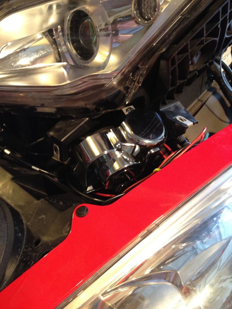
There is a space on the left side of the RT under the fascia trim which turns out to be perfect for mounting a 139dB Stebel Nautilus Dual-tone Air Horn.
For reasons not explained, the manufacturer would like the Nautilus to stand vertical side-to-side and fore-and-aft. The space I've chosen for this will acommodate the Nautilus as near perfectly upright as makes no difference!
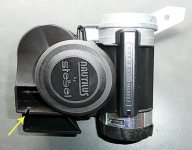
Photo #1 shows the Nautilus. The yellow arrow points to a small cutout I made to the upper horn to allow it to slot around the left bracket. (See arrow in photo #4 for where this fits). The bright metal piece sticking up and out to the right of the horn is the mounting bracket I made out of aluminium.
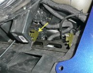
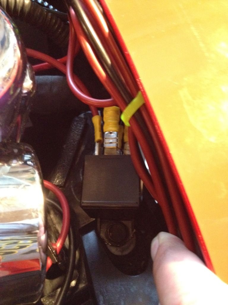
Photo #2 shows the aluminium bracket holding the Nautilus in position. The bracket has to be cut as shown in photo #1 to allow the RT's fascia to be fastened in place. A hole has to to drilled into the projecting fascia support to allow a bolt through for the bracket and the relay.
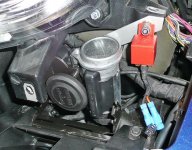
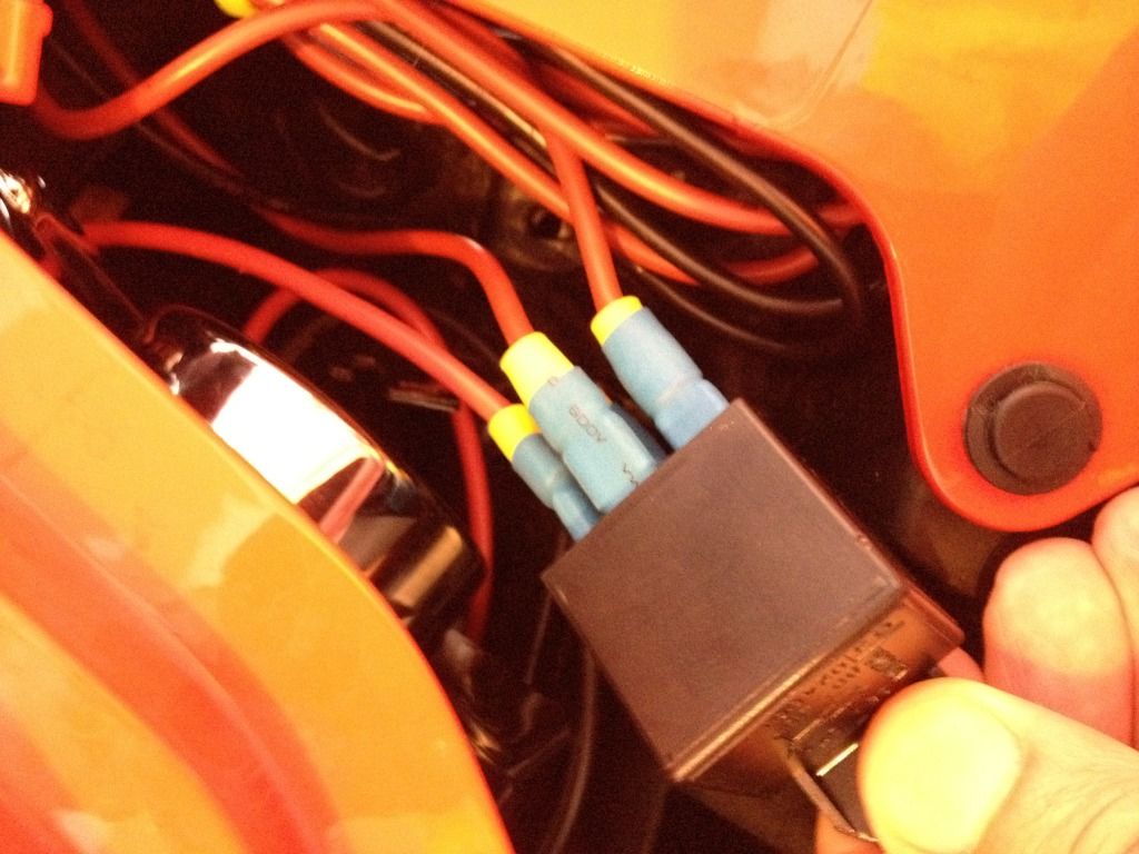
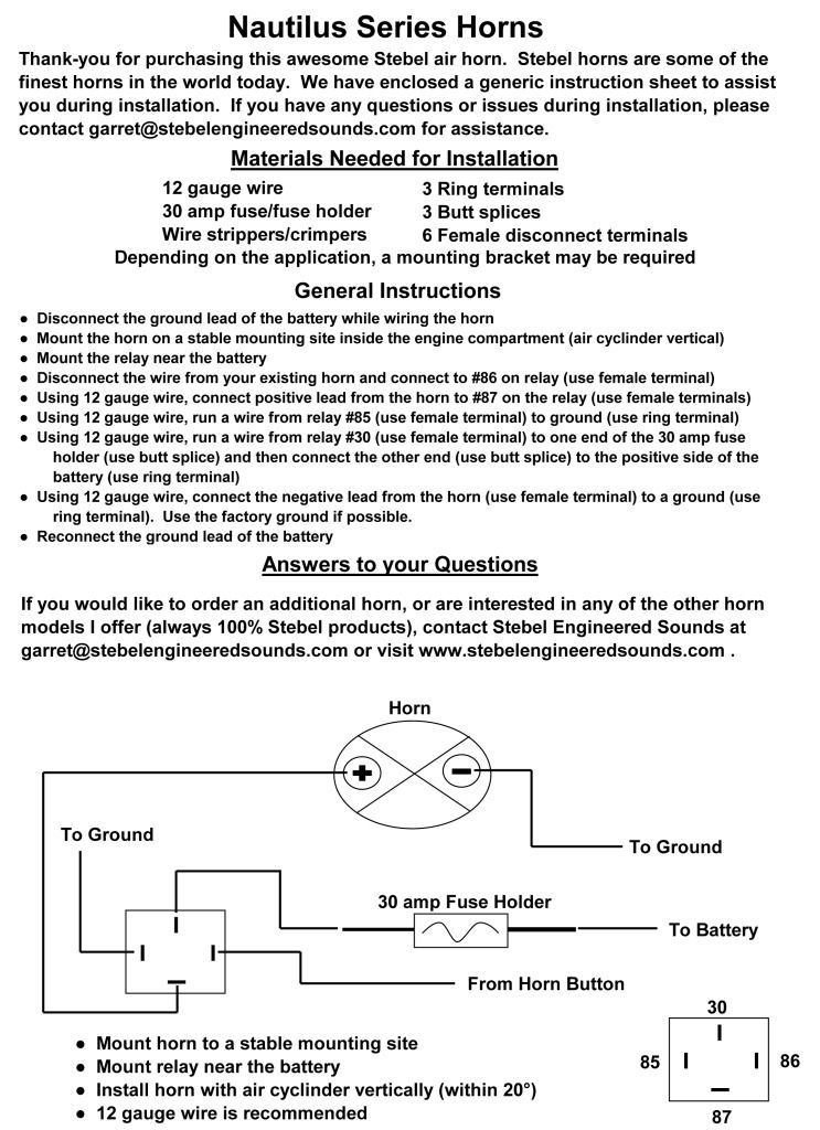
Photo #3 Shows the Nautilus in position. Note the 2 blue Positaps taking the horn push wires to the relay. The RT's wire colors are Blue/beige (+) and Green/grey (-). Using a relay, (supplied with the Nautilus), to connect a 20amp supply direct from the battery is the prefered option. The wiring for the RT's existing horn is insufficient for prolonged use of the Stebel. For full volume output the horn manufacturer recommends a dedicated 20 amp supply.
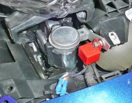
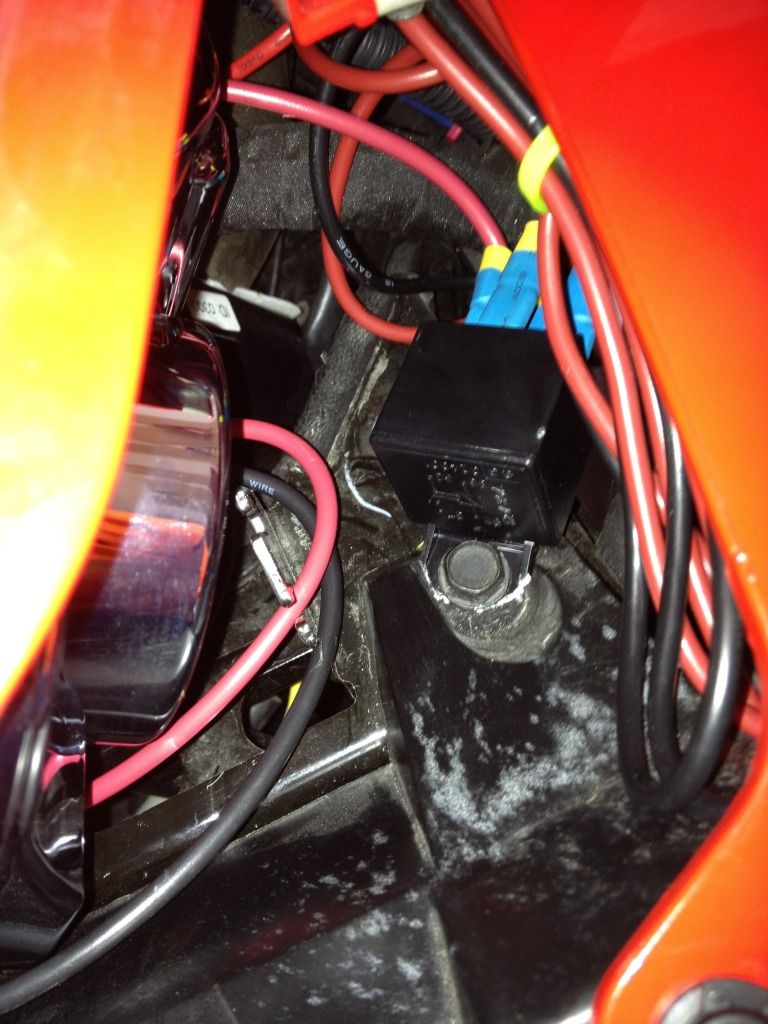
Photo #4 shows the location I used. There are a pair of BRP brackets, (color-washed yellow), which it seems are not used for anything at all. The yellow arrow shows where the cut-out I made in the plastic of the upper Nautilus horn in photo #1 slots onto the bracket.
Look out for a further post from me on this installation dated 04-28-2013. Heading:
 Stebel Nautilus Horn Mount VIBRATION PROBLEM and CURE
For reasons not explained, the manufacturer would like the Nautilus to stand vertical side-to-side and fore-and-aft. The space I've chosen for this will acommodate the Nautilus as near perfectly upright as makes no difference!
Photo #1 shows the Nautilus. The yellow arrow points to a small cutout I made to the upper horn to allow it to slot around the left bracket. (See arrow in photo #4 for where this fits). The bright metal piece sticking up and out to the right of the horn is the mounting bracket I made out of aluminium.
Photo #2 shows the aluminium bracket holding the Nautilus in position. The bracket has to be cut as shown in photo #1 to allow the RT's fascia to be fastened in place. A hole has to to drilled into the projecting fascia support to allow a bolt through for the bracket and the relay.
Photo #3 Shows the Nautilus in position. Note the 2 blue Positaps taking the horn push wires to the relay. The RT's wire colors are Blue/beige (+) and Green/grey (-). Using a relay, (supplied with the Nautilus), to connect a 20amp supply direct from the battery is the prefered option. The wiring for the RT's existing horn is insufficient for prolonged use of the Stebel. For full volume output the horn manufacturer recommends a dedicated 20 amp supply.
Photo #4 shows the location I used. There are a pair of BRP brackets, (color-washed yellow), which it seems are not used for anything at all. The yellow arrow shows where the cut-out I made in the plastic of the upper Nautilus horn in photo #1 slots onto the bracket.
Look out for a further post from me on this installation dated 04-28-2013. Heading:
Attachments
Last edited:
")

 pps:
pps: