• There were many reasons for the change of the site software, the biggest was security. The age of the old software also meant no server updates for certain programs. There are many benefits to the new software, one of the biggest is the mobile functionality. Ill fix up some stuff in the coming days, we'll also try to get some of the old addons back or the data imported back into the site like the garage. To create a thread or to reply with a post is basically the same as it was in the prior software. The default style of the site is light colored, but i temporarily added a darker colored style, to change you can find a link at the bottom of the site.

How To Properly and Stylishly Mount Mutazu Bags To An F3S - with pics

spider bag emblem

this thread on the Matazu bags has become a good one for those of us who have them or want to get them.
Install instructions by Trevor with pics should be a format all should follow when they post DIY stuff.

I got the spider emblems on Ebay as no vendor here has them in the size and type to fit.
I have provided the source to a couple folks already, so PM me if you need more info.
 
Last edited:
Under The Seat Panel - Replacing The T Nuts

Under The Seat Panel

Replacing The T Nuts

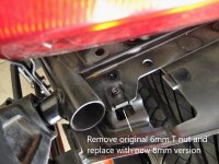
3) When you lift the seat panel you will see a 6mm T nut on each side, which needs to be removed. The screws that held each of those small covers in place go into the 6 mm T nuts

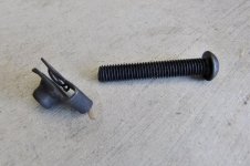
In its place on each side we put an 8mm T nut purchased separately. The top stabiliser brackets will be bolted on each side to this same point and also hold the covers in place.

Use a flat blade screw driver and slip-joint pliers or multigrips to remove the T nuts. If you examine the new ones you will see that on the underside there is a small projection which locks or locates the T nut in the hole. The idea is to spread the two sides of the T nut just enough to let this locking locater slide out of the hole.

Position the new 8mm T nut in the centre of the hole.

Replace T nut.jpg

Refit the cente screw to the main under-guard cover.

Now insert the 50mm x 8mm button head bolt into the small cover on each side. It won't slide in but it will screw in. Don't open up the hole with a drill - use its size to help hold the button head bolt in place.


Reposition the cover and make sure the bolt will screw into the new T nut. If not, you might just have to reposition the T nut slightly on the flat metal bracket. (Don't try to screw the bolt in all the way - it needs a spacer, washers and bracket on it to be the correct length.)

After test fitting remove the bolt and the cover.

Insert and tighten the 5 screws in the under-seat cover.

DSCF2219.jpg
 
Last edited:
Preparing The Top Stabilising Bracket - Drilling The Extra Hole

There are two types of standard size right angle brackets supplied in the kit, four right angle brackets in total, which have equal length sides. (We have already used the 2 brackets which have an extended side, on the rear hanger.)

Ignore the two standard size right angle brackets with a large hole on one arm; they will be used without modification.

The two remaining brackets have 3 holes in each arm. We need to drill an extra hole closer to the bend, and then cut off the extra length on that arm. This then becomes the top stablising bracket. (The extra length would catch on the tyre on large bumps.)

Look carefully at the bracket - on one arm of each the existing holes are drilled slightly closer to the bend. This is the side that we will add the hole to. When we do this the three stabilising brackets fit in perfectly!

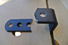
Bolt the two sides of the standard right angle brackets together, back to back, along the edge that the hole(s) needed to be added to.

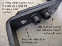
Mark and drill each bracket from the opposite side.

Drill brackets back to back.jpg
 
Last edited:
Notes On Drilling Holes

After bolting up back-to-back the two brackets that need extra holes, be careful when marking the centre to start drilling.

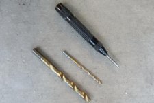
Use a hand-held automatic centre punch in good light, to make sure you have the right spot. Turn the brackets around 180 degrees to obviate parallax errors.

Drill a pilot hole all the way through with a 5/32" bit, or equivalent metric size. Use a slow speed on the drill and gradually speed up to get a good flow of swarf from the bit. Not too fast, though, it could overheat and become dull. The best speed gives the best flow.

Use 5/16" or 8mm to make the full size hole, using the slowest possible speed.

DSCF8849.jpg
 
Finishing The Holes

Finishing The Holes

There will be raised edges on the holes after you finish drilling.

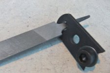
You can remove these either by using a larger bit held in your hand and rotated a few times on the edge of the hole, or by using the curved edge of the handle of a file which you also rotate in the hole.

When the edge of the hole is smooth (this is very important to make sure that the brackets bolt together tightly) you can add some satin black paint to match the rest of the bracket.

DSCF8851.jpg
 
Preparing The Top Stabilising Bracket - Cutting Off The Excess Length

Preparing The Top Stabilising Bracket

Cutting Off The Excess Length


Time to fire up the angle grinder, after fitting it with a cutoff disc.

Make sure you wear ear plugs and eye protection. Only use an angle grinder outside of the garage, with the door shut, to prevent ther sparks igniting a fire from fuel or oil remnants.

Cut it off at the second hole from the bend, next to the one you just drilled.

Angle the cut to the edge of the hole, from each side, and then round off this section of the bracket using a grinding/finishing disc.

Use a file to remove the sharp edges remaining.

DSCF2225.jpg
 
Last edited:
Summarising The Bracket Modifications

Summarising The Bracket Modifications

At this stage the following essential modifications should have been made:

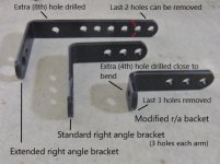
1) The front hanger - bottom section cut off, about 3/16" below the bottom hole - to allow the spacer which connects to the saddlebag frame to correctly fit in.

2) The extended right angle bracket - an extra, 8th hole drilled close to the bend. The 7th hole is not drilled.

3) The standard right angle bracket - it has 3 holes on each side. An extra hole is drilled on the side with the holes closer to the bend, then the excess length of this side is cut off at the second hole (the one adjacent to the new one drilled).

This then becomes the top stabiliser bracket.

right angle brackets.jpg

Non-essential modification:

4) You could cut off the bottom 2 holes from the extended right angle bracket, so that this bracket projects below the saddlebag frame the same amount as the third hanger does on the front mount. Now is the time, if you are going to do it!

Once the painting is done, the system can be assembled. You can also paint each bracket as it is modified, rather than leave it all to the end of the mods.
 
Last edited:
Painting The Modified Brackets

Painting The Modified Brackets

Please ensure that any raised edges on the holes or where brackets have been cut, are removed, to ensure a strong fit to the adjacent bracket or bolt.

Place the brackets on their edge.

Spray 3 or 4 light coats from about 12" away.

A light coat is one which still looks dull and dry. A heavy coat is one which looks wet and thick, and runs. It will take a day to dry properly.

Don't try to cover all the bare metal with the first coat - the paint should be touch dry in 60 seconds to allow you to turn the brackets over on their other edge.

Turn the brackets around, as well, so that you are painting from the opposite side or angle.

Multiple light coats at one or two minute intervals will produce good cover which will be touch dry in minutes, and usable in about half an hour.
 
Tougher Paint

Painting The Modified Brackets

Please ensure that any raised edges on the holes or where brackets have been cut, are removed, to ensure a strong fit to the adjacent bracket or bolt.

Place the brackets on their edge.

Spray 3 or 4 light coats from about 12" away.

A light coat is one which still looks dull and dry. A heavy coat is one which looks wet and thick, and runs. It will take a day to dry properly.

Don't try to cover all the bare metal with the first coat - the paint should be touch dry in 60 seconds to allow you to turn the brackets over on their other edge.

Turn the brackets around, as well, so that you are painting from the opposite side or angle.

Multiple light coats at one or two minute intervals will produce good cover which will be touch dry in minutes, and usable in about half an hour.
:agree: ............ and let me add that you can easily make the Paint tougher by putting it a 275 degree oven and letting it bake for 10 minutes after it has thoroughly Dried ..... If you do it sooner it will smell....After the volatiles have dried it bakes with only a minor smell ...... I just did my re-painted car wheels ...... Mike :thumbup: ......PS do not do this on Plastic
 
Last edited:
Fitting The Top Stabiliser Bracket

Fitting The Top Stabiliser Bracket

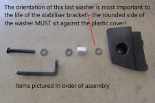
Take the button head 50mm x 8mm bolt purchased as extra and start fitting to it:

1) flat washer (rounded side against bolt head)

2) top stabiliser bracket (into the extra hole in the short arm)

3) flat washer (flat side against bracket)

4) 3/4" x 5/16" spacer purchased as extra

5) flat washer - flat side against spacer. The rounded side of this washer MUST fit against the plastic cover.


Upper stabiliser mounting.jpg


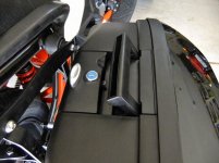
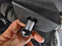
Insert the end of the bolt with components attached into the hole in the plastic cover removed earlier and screw it into the hole until at least a 1/2:" of thread is sticking through the cover.

Fit the edge of the cover closest to the tyre first, then wriggle it into place and screw the button head bolt into the 8mm T nut you fitted earlier. Screw this up until almost tight. Leave it loose enough so that the stabiliser bracket can rotate and tilt a little.


DSCF2239.jpg
 
Last edited:
Rear Stabiliser Brackets Summary

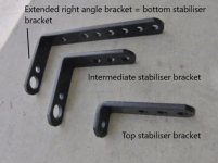
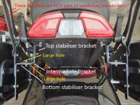
Here are the three brackets used to stabilise the bags at the rear.

The largest bracket, which I have called the extended right angle backet, is already mounted to the back of the rear hanger.

The shortest bracket, which I have called the top stabiliser bracket, should be mounted into the small plastic cover mounting hole at the rear of the under-guard area.

The third bracket with equal length arms and the large hole is the intermediate stabiliser bracket and will connect the other two stabiliser brackets together.

Stabiliser brackets.jpg
 
Bottom Rear Stabiliser Bracket

Here is the bottom stabiliser bracket ready to receive the intermediate stabiliser bracket.

Note the large hole in this arm - one arm in the intermediate bracket also has a large hole, and these two large-hole sides are placed together.

Bottom stabiliser.jpg
 
Assembling The Stabiliser Brackets

Assembling The Stabiliser Brackets

1) Take the intermediate stabiliser bracket and place it on top of the extended right angle bracket, placing the side with the large hole in contact with the large hole arm of the extended right angle bracket. These arms are horizontal.

The vertical arm of this bracket should now be pointing up, and adjacent to the down-pointing arm of the top stabiliser bracket recently fitted into the plastic cover.

Insert a 20mm round head bolt with a washer through the centre hole of each bracket, and tighten the nut by hand - this leaves some wriggle room to help connect to the uppermost stabiliser bracket.

2) Screw the 8mm button head bolt which holds the top stabiliser bracket into the plastic cover. Make it finger tight, using the short end of an allen key for leverage.

Check the hole alignment between the intermediate and top brackets, Some vertical misalignment, up to about 1/3 of a hole up or down, is OK.

Any more misalignment and you might need to add or remove a washer between the top stabiliser bracket and the 3/4" spacer. There is one in there now.

Stabiliser brackets complete.jpg

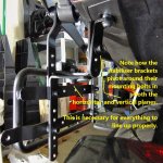
Horizontal misalignment will be taken care of by swivelling the intermediate and top brackets until their vertical arms come together. Insert a 20mm round head bolt and washer into the middle hole and tighten finger tight.


Stabiliser close up.jpg


Note how each bracket has to pivot slightly around its mounting bolt for everything to line up properly.


3) Check the alignment of the three brackets and then gradually tighten the two bolts on the intermediate bracket. One is on the horizontal arm, one is on the vertical arm.

A small amount of tension between the three brackets will not be a problem, but if the saddlebag frame or any of the brackets start to tilt or distort there is something not right.

4) At the same time fully tighten the 8mm button head bolt which holds the top stabiliser bracket into the small plastic cover, and holds them both onto the frame of the bike.

It is important to use moderate force only to tighten this. The top stabiliser bracket should be firmly mounted, but if you insert the final washer the wrong way or use excessive force you could possibly cut a hole in the plastic cover, the size of the washer, so that the cover eventually drops down.

 
Last edited:
Final Checks

Check that all mounting bolts are tight.

Push against the sadllebag frame to make sure it does not move inwards - there should be no slop or flex or movement on any component.

Take a bag and insert the recesses on the bottom into the two Y-shaped spacers on the bottom of the frame.

Push the top of the bag inwards towards the bike - there will be a loud, obvious click when the top mount is connected.

Insert the red key supplied and turn the lock a 1/2 turn with the bag handles up. (The lock slot will be at right angles to the bike.)

This locks the top attachment to the bags but allows you to open the bags at any time without the key. Once the bag is locked you can then lower the handles.

To lock the bags themselves, leave the handles all the way down when turning the key. This locks the handles, and the bags to the frame.

DSCF2321.jpg

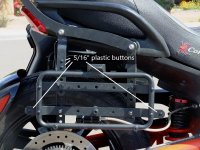
When you are satisfied that all is good, add the 5/16" plastic buttons to the holes in the mounting frames which you do not want to be visible, to hide the Meccano effect. ;-)

The buttons are easily dislodged if you brush against the back of them, but don't come out in normal use. To make them more secure just add a dab of RTV sealant (silicon gasket) material to the back of them before inserting.

Plastic buttons.jpg
 
Last edited:
Fitting The Bottom Plates To The Bags

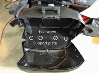
Two bottom plates are supplied, which support a liner bag or other luggage when the case lid is open.

They will only go in one way - check the picture - and small screws are supplied in with the wiring kit to fix the plates to the bottom of the case.

I have not yet done the wiring - the tricky part, mounting the cases, is now complete.

Finis

Support plate.jpg
 
Adding Liner Bags

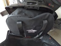
Use saddlebag liners from Bestem for BMW R1100, K1200, model LGBM-K12GT-SDL

BMW oem liner bags and from most other suppliers have an extra pocket which sticks out on the inner side, designed to fit into a recess in the BMW oem cases. There is no such recess in the Mutazu, or any other bags that I know of.

Bestem bags do not have these extra pockets, and so will fit nicely.

About $53 from Amazon.

DSCF8957.jpg

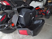
The liners might look on the small side here, but when you fill them they will bulge out, and if you are not careful how you pack, make the lid hard to close.

However, they protect the inside of the saddlebag from inadverttent damage from sharp and hard items rattling around, and make it very easy to carry all your travel items in in two hands when you arrive.

You can also fit small, soft items in the gaps left when the filled liner bag is placed in the side case.

DSCF8958.jpg
 
The Last Word(s)

If you live in the Phoenix area or don't mind travelling I am happy to install your Mutazu bags.

The cost of the extra components is around $40. Install labour is $110, not including wiring of the lights.

Message me if interested.

If you are handy with assembly but lack the tools or skills or just aren't interested in doing the modifications yourself, I will modify your kit for $60, plus postage both ways.
 
Stabilising The MBL Rack

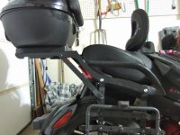
If you also have an MBL rack fitted and don't like the way it bounces up and down on the road (or when you put any pressure on it at a standstill), here is a simple way to stabilise it.

The Mutazu mounting method I devised does not need the long support arms they supply for connecting the bags across the bike.

Instead, I fitted them as shown and the bouncing is completely eliminated. All that is needed is to drill two extra holes, one on each side of the rack, to make the connection.

Where previously it was most uncomfortable for me to ride pillion, because the bouncing of the rack meant that the back rest on the top case was constantly bouncing into my back, now it is still and I can even lean back in comfort.

DSCF8858_1.jpg
 
Last edited:
Back
Top