• There were many reasons for the change of the site software, the biggest was security. The age of the old software also meant no server updates for certain programs. There are many benefits to the new software, one of the biggest is the mobile functionality. Ill fix up some stuff in the coming days, we'll also try to get some of the old addons back or the data imported back into the site like the garage. To create a thread or to reply with a post is basically the same as it was in the prior software. The default style of the site is light colored, but i temporarily added a darker colored style, to change you can find a link at the bottom of the site.

Fog lights won't work

The big connector must be 16 pin or more, not 6, right? Tell me exactly what color wires go to each piece, main color + trace color. Something doesn't seem to be matching up on the wiring diagram. It shows two of the wires going to the relay as being on the bike already. I really don't think the four wires with the terminals go into the four pin connector. They must go into a connector that is on the bike already. BRP doesn't plug loose terminals into connectors, nor send out loose wires unless they are to be put into existing
connectors.

**It looks to be a 14 pin but there are only 4 wires inside of it (see pic). I've attached pic to see colors of wires. As far as the 4 wire from switch, I did see a connection just sitting there with nothing hooked into it.**


Are you sure the pieces are exactly as they come from BRP in the kit? Have you plugged some wires into some connectors already? If not, then I suspect someone has plugged some wires into some connectors where they don't belong. Is this kit supposed to be for a 2013 RS? The two three pole connector housings are blanks you took off of the connectors to plug the fog lights in, right?

**All parts are what I received from seller and he states that everything he used was sent. The only connections I made to the bike was plugging in the fogs to the 3pole connections in place. The kit is for the 13 models. I specifically asked before purchasing them. Yes,. The 3 pole connections were removed from the fogs when I hooked them up on the bike.**


Let me know what all you can tell me. We'll get this figured out somehow.

**I will be taking the panels off today to check for connections that you suggested. I remember seeing a square connection with nothing plugged into it but nothing from the kit fit. I appreciate your help. Maybe I missed something somewhere.**
 
**I will be taking the panels off today to check for connections that you suggested. I remember seeing a square connection with nothing plugged into it but nothing from the kit fit. I appreciate your help. Maybe I missed something somewhere.**
That helps a lot. It'll be later today before I can take the time to study the wiring diagram, which I'll post some parts for you to see. The big connector, which I'm sure is PIC1 for panel interconnector, has 8 or more wires in it so the switch wires may well plug into it. When you finally find the mating connector on the bike make a note of the colors and positions of all the wires going into it so we can match the wires on this connector.

Yes, the prong on the connector is to anchor the connector to the frame. You should find a blank connector that looks the same as this one. It very well may on the inside of the frame and not obvious when you're looking. Same for the smaller square on except it will probably be not be anchored.
 
**I will be taking the panels off today to check for connections that you suggested. I remember seeing a square connection with nothing plugged into it but nothing from the kit fit. I appreciate your help. Maybe I missed something somewhere.**

Well,.. I found the connection on the left side of bike that fits the harness. I plugged into that, ran the switch wires through plug that fits other end of harness. Everything fit like it should but when trying to start bike the fuse blew to my display and no power to it. The bike still started, but fogs didn't work!!! I thought maybe I had the pin wires crossed so I re-wired and tried again. No go for fogs!! See pics below for how I hooked it up.


This has to be the right connection !?!? Maybe now I need to figure out wiring???
 
OK, I've got it figured out now, at least according to the wiring diagram.

There are only 4 wires going into the 14 pin connector, PIC1. You have it plugged in correctly. The square connector is the fog light switch connector, FGS, so I had it wrong. Do you have the female housing part that the male terminals from the switch go into? You don't show it in the pics or is that it in the last photo? If you haven't figured out how to put that connector together do a search for "deutsch dt connector assembly instructions." The video by LADD looks like it is good. But plug the terminals into the other half first to make sure all is OK before you put them in the connector permanently. They're a pain to get back out if you get them wrong!

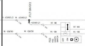
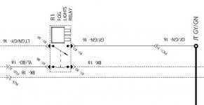
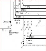
The four wires of the switch plug into FGS like this (Switch to Connector): Black to Yellow/Red; Blue to Black; Red to Orange/Red; and Black to Light Green/Gray. The two blacks are interchangeable. There's a black wire from the relay, and the one from the switch. They join together in the harness at a diode which then is connected to PIC1 with the black wire. The diode is under the harness wrap somewhere. I left this detail of the diagram out of the segments below.

Here's some of the wiring diagram, in segments to avoid photo limitations of the site. 1st one is left, or top, the 2nd right, or bottom. The third segment shows the black wire from the diode connecting into PIC1. They are quite a way apart on the wiring diagram even though next to each other in real life.

Does this get you all fixed up, I hope!

RS wiring 1 left.jpgRS wiring 1 right.jpg RS wiring 2.JPG
 
Last edited:
OK, I've got it figured out now, at least according to the wiring diagram.

There are only 4 wires going into the 14 pin connector, PIC1. You have it plugged in correctly. The square connector is the fog light switch connector, FGS, so I had it wrong. Do you have the female housing part that the male terminals from the switch go into? You don't show it in the pics or is that it in the last photo? If you haven't figured out how to put that connector together do a search for "deutsch dt connector assembly instructions." The video by LADD looks like it is good. But plug the terminals into the other half first to make sure all is OK before you put them in the connector permanently. They're a pain to get back out if you get them wrong!

The four wires of the switch plug into FGS like this (Switch to Connector): Black to Yellow/Red; Blue to Black; Red to Orange/Red; and Black to Light Green/Gray. The two blacks are interchangeable. There's a black wire from the relay, and the one from the switch. They join together in the harness at a diode which then is connected to PIC1 with the black wire. The diode is under the harness wrap somewhere. I left this detail of the diagram out of the segments below.

Here's some of the wiring diagram, in segments to avoid photo limitations of the site. 1st one is left, or top, the 2nd right, or bottom. The third segment shows the black wire from the diode connecting into PIC1. They are quite a way apart on the wiring diagram even though next to each other in real life.

Does this get you all fixed up, I hope!

View attachment 86100View attachment 86101 View attachment 86103

So it looks like I did have the pins in wrong which is why I blew a fuse?? I'm off tomorrow so I will try the diagram in the morning. I hope it works!! Thanks again , will let you know results.
 
Sounds like you may have got it if they still don't work I can pull off the panels and take pics of the connectors and location but there pretty much plug and play once the connector is assembled

I did the BRP HIDS on my 13 that took a little bit of figuring but still wasn't hard
 
Yep, accidentally connecting power to ground will do it every time! :) That's why every circuit needs to be protected by a fuse! :lecturef_smilie:

I think you've got it made now!

YEESSS!!!!! They work!!!! :2thumbs:

Thanks for all of your help!! :bowdown:
 
Sounds like you may have got it if they still don't work I can pull off the panels and take pics of the connectors and location but there pretty much plug and play once the connector is assembled

I did the BRP HIDS on my 13 that took a little bit of figuring but still wasn't hard

Yes,.. Finally!! At least now I know more about the bike and taking it apart. I will most likely upgrade to HIDs soon. For now, are there any upgraded replacement bulbs that will give you better output than stock ones? I also installed the tricled light rings and difference of the two is very noticeable.
 
There are better bulbs you can get , just watch going higher wattage could damage the wiring due to the higher amp draw.

If you wanna do HIDS depending on what you decide I would just go for those . Sylvania silver star bulbs are almost $50 a set the aftermarket HID kits don't cost much more then that. I installed the BRP hid kit and thats the way to go if you wanna swing the extra cost. I got mine from a dealer that was on clearance since BRP say they only fit 2012

I can tell you that they do work on 2013 by simply cutting and soldiering the 2 small jumper headlight harness. If you can soldier the wiring is a piece of cake.

Install is little involved since you replacing both the headlight assemblies and not just adding bulbs and ballasts.
 
YEESSS!!!!! They work!!!! :2thumbs:

Thanks for all of your help!! :bowdown:
:clap::clap::clap::clap:
Glad I could help. I'd hate to think all the time I spent poring over the wiring diagram would have been wasted!!:roflblack: Thanks for getting back with all the pics and such. That really helped me get it figured out!:thumbup:
 
There are better bulbs you can get , just watch going higher wattage could damage the wiring due to the higher amp draw.

If you wanna do HIDS depending on what you decide I would just go for those . Sylvania silver star bulbs are almost $50 a set the aftermarket HID kits don't cost much more then that. I installed the BRP hid kit and thats the way to go if you wanna swing the extra cost. I got mine from a dealer that was on clearance since BRP say they only fit 2012

I can tell you that they do work on 2013 by simply cutting and soldiering the 2 small jumper headlight harness. If you can soldier the wiring is a piece of cake.

Install is little involved since you replacing both the headlight assemblies and not just adding bulbs and ballasts.

Thanks for the info. :thumbup:
 
:clap::clap::clap::clap:
Glad I could help. I'd hate to think all the time I spent poring over the wiring diagram would have been wasted!!:roflblack: Thanks for getting back with all the pics and such. That really helped me get it figured out!:thumbup:

Just submitting a pic of all of my hard work!! :ohyea:
8F09B4E8-3A49-461E-B58D-1BDB083EB3F9.jpg
 
Back
Top