• There were many reasons for the change of the site software, the biggest was security. The age of the old software also meant no server updates for certain programs. There are many benefits to the new software, one of the biggest is the mobile functionality. Ill fix up some stuff in the coming days, we'll also try to get some of the old addons back or the data imported back into the site like the garage. To create a thread or to reply with a post is basically the same as it was in the prior software. The default style of the site is light colored, but i temporarily added a darker colored style, to change you can find a link at the bottom of the site.

Fog Light Switch Wiring Question

Wildchild6969

New member
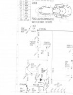
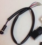
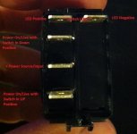
I took out the factory fog light switch on my Spyder. It was connected to 4 wires. One red, one blue and two black wires with writing on them. Does anybody know where these four wires are meant to lead to? I'm trying to install a 3 wire illuminated switch in place of the factory 4 wire one. A related wiring diagram would be awesome.
 
A few years back I had one of those switches that I considered using for some aux. lights. Using a multimeter I remember there was power/ground for the led and then the other two connections for the make/break switch. Don't know how that works in relation to wire color but would be pretty easy to figure out. Time to pull out your multimeter!👍
 
Let me look and see if I either still have the pic with the wiring diagram, or if I can find the switch I'll double check the pins.
I just haven't looked at any of that for quite some time....I'll look though.
 
Hey Rodney,
Here is the pic I did before when this questions was brought up awhile back. This shows the switch pin designations.
Hope this helps.
 

Attachments

  • Foglight Switch.jpg
    Foglight Switch.jpg
    35 KB · Views: 166
It's the illuminated pin switch type like this one...

Hey Rodney,
Here is the pic I did before when this questions was brought up awhile back. This shows the switch pin designations.
Hope this helps.

This type... Anyone? Please help...
 

Attachments

  • image.jpg
    image.jpg
    24.2 KB · Views: 89
Here's a picture of the switch and the wires.

attachment.php
This is the switch and the four colors that I need to know the designations.

Thanks
 

Attachments

  • image.jpg
    image.jpg
    27.9 KB · Views: 330
yea, Sorry about that. Wrong switch... If I had to guess, I'd say that the red and blue are the make/break for the switch control and the two blacks are for the bulb.....BUT It's possible that one of the blacks is a ground, and the other is the light control that gets its power from the red when the switch is turned on......Time to break out the volt meter!...;)
 
Last edited:
No volt meter here

yea, Sorry about that. Wrong switch... If I had to guess, I'd say that the red and blue are the make/break for the switch control and the two blacks are for the bulb.....BUT It's possible that one of the blacks is a ground, and the other is the light control that gets its power from the red when the switch is turned on......Time to break out the volt meter!...;)

I was just hoping that someone on here would know for sure. Can't find the answer anywhere on the interweb...
 
yea, Sorry about that. Wrong switch... If I had to guess, I'd say that the red and blue are the make/break for the switch control and the two blacks are for the bulb.....BUT It's possible that one of the blacks is a ground, and the other is the light control that gets its power from the red when the switch is turned on......Time to break out the volt meter!...;)


2 wires are the push button switch, one goes to the light inside the switch,and one is ground
for the light , I will look at mine tomorrow and send you a private message.
 

Attachments

  • image.jpg
    image.jpg
    32.2 KB · Views: 109
Last edited:
Get a cheap meter. Usually the blacks are grd/negative. One black is for the LED and the other probably for the load/foglight. The meter is the easiest way to find out what is connecting when the switch is flipped.
 
Spyderlovers group

I can't believe that these four fog light wires have stumped this group of Spyderlovers.
 

Attachments

  • image.jpg
    image.jpg
    27.9 KB · Views: 43
Get a multimeter. I removed my suggestion because I ran across conflicting wiring installations. I'll keep checking.
 
Last edited:
It plugs into the fog light harness.You need the installations papers that comes with the fog light kit. I can't Believe you want to replace a four wire switch with a three wire switch. Why not replace it with a four wire illuminating switch. I have the 09 GS Phantom.
 
Last edited:
Installing LEDs

It plugs into the fog light harness.You need the installations papers that comes with the fog light kit. I can't Believe you want to replace a four wire switch with a three wire switch. Why not replace it with a four wire illuminating switch. I have the 09 GS Phantom.

The reason that I am replacing the factory switch is because I installed neon lights underneath and I want the two switches to match so I bought two new illuminated switches that I like and that would fit together etc... I still haven't got the factory switch wires figured out. It's not the traditional red is hot and black is ground. I used a test light and the red has no power and the blue appears to be the ground.

In summary I believe that the red runs to the headlights, one of the black runs to the fog lights, the blue is the ground and the other black does nothing at all no matter what position the key or light switch is in. I was hoping that among all the Spyder lovers someone would have a definitive answer on this wiring diagram but still no luck. It is the factory 2008 Spyder GS SM5 foglights switch nothing after market or anything. Thought this would be a simple swap of switches but not been so far lol...
 
Back
Top