• There were many reasons for the change of the site software, the biggest was security. The age of the old software also meant no server updates for certain programs. There are many benefits to the new software, one of the biggest is the mobile functionality. Ill fix up some stuff in the coming days, we'll also try to get some of the old addons back or the data imported back into the site like the garage. To create a thread or to reply with a post is basically the same as it was in the prior software. The default style of the site is light colored, but i temporarily added a darker colored style, to change you can find a link at the bottom of the site.

Finally got around to finishing the 18x8" front wheel mods ... sweet !

fatenhappy

New member
Seems like there has been millions of things happening during the passed few months, so the Spyder's mods have been on the back burner ?

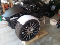
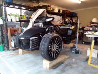
Finally just this week, I thought I'd strike a blow as the custom wheels have been sitting in the garage for about 2 or 3 months or so. I really wanted to set up the basic platform so I can move on with Cathy's the side car project.

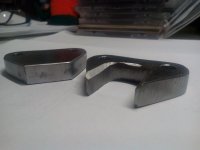
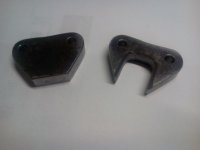
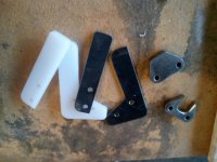
Part 1 went really well a while back in that the 3 to 5 stud wheel adapters worked out fantastically.

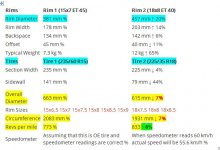
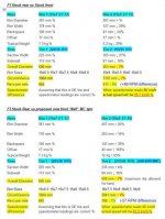
The real problem is I did not count on the F3's computer being quite so finitely calibrated with the differential between the front and rear wheels in their 'turns ratio' which is fed for such things as ABS, Anti-Skid etc.

For the uninitiated, the Can Am Spyders have different sized wheels (finished diameter after their respective tyres are fitted up - as standard) front and back. However the onboard computer has been precisely calibrated for that differential. So what you may say! Simply put as I found out the hard way if you are going to mess about with different diameter wheels the original front to back differential ratio has to be maintained.

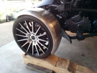
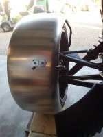
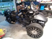
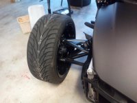
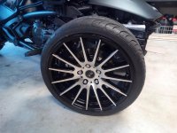
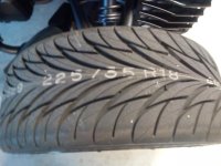
So after all that, this is the way things have finally finished up just as of this afternoon. Jobs done ... 18x8s on the front ... but I had to go up two profile sizes from a 50 to 60 profile for the rear plus increase the width from a 225mm to a 235mm (which also added to the tyre diameter by 1/2".... which made all the difference.

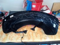
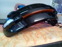
Maths reworked and done, application applied and I am wrapped ... Everything is perfect with now only the replacement front mudguards to be further customised for their new 'special fit' ?

So finally, next comes Cathy's side car project ?

The new rear wheel tolerances were pretty tight, but with a rear wheel re-centering also done etc, in the end everything has worked out really well ?

Nanny's happy, I'm happy ? The only down side is with the speedo now under reading by about 3 kilometres per hour, but that is not a problem either as such as I ride using my GPS ? sweet !
 

Attachments

  • IMG_20181116_182516.jpg
    IMG_20181116_182516.jpg
    64.8 KB · Views: 332
  • IMG_20181116_181407.jpg
    IMG_20181116_181407.jpg
    45.7 KB · Views: 235
  • IMG_20181116_181323.jpg
    IMG_20181116_181323.jpg
    64 KB · Views: 229
  • IMG_20181116_182413.jpg
    IMG_20181116_182413.jpg
    61 KB · Views: 234
  • IMG_20181116_181336.jpg
    IMG_20181116_181336.jpg
    48.2 KB · Views: 206
Last edited:
Just as an aside ? here's the maths that goes into the wheel change between sizes ? Just maintain the front to back differential and nanny is happy ! This sort of thing can be found for doing the comparisons directly on any reputable wheel sizing web site. I used wheel.com ? every things there to poke around with ? Simple! ? https://www.wheel-size.com/calc/
 

Attachments

  • 18x8 wheel comparison required front to rear.JPG
    18x8 wheel comparison required front to rear.JPG
    52.6 KB · Views: 45
  • Wheel tyre comparison rear wheel to 18x8 MC Front.jpg
    Wheel tyre comparison rear wheel to 18x8 MC Front.jpg
    46.3 KB · Views: 32
Last edited:
Oddly, we all tend to reference the charts. Surprised no one has ever done a measured roll out to see exactly what tne numbers are on stock Kenda tires.

Chalk mark tire near floor, roll forward by hand until chalk mark has made one rev. Measure roll out length.

If the fronts match the rear there roll out is equal. If not, the percentage change can be noted and retained with tire swaps.
 
Looks good!
Keep us up to date on the mud guard (fender) progress.
Also give a ride report on how she handles with the big shoes.
 
From the little bit of riding I have done on it since … it feels firm and sure footed … Having said that, I'm hoping to get it in for a wheel alignment earlier this coming week!
 
My left leg and its associated prosthetic has been playing up something shocking for the passed couple of days so I could only get going back on things today, all be it in my wheel chair for the time being.

The idea is to fit up the new 250mm / 10" guard (which has to be that wide to accommodate the round support tubes) that come up from the axle assembly, using the stock mounting tubes if at all possible.

My prior thoughts were to make a set of 12mm (1/2") mounts for each of the two mounting points for each wheel. Prior, I was unsure if stock brackets height would also need attention …

To my almost astonishment everything was spot on. The stock F3-T mounts will fit for height by about 1/2" clearance no problem. Now all that seems to be needed is to make qty 4 of the 1/2" standoffs (spacers) to mount to compensate for changing from a 17 ET to a 40 ET.

To date I am planning to spray the new guards matt black to match the stock paint scheme already on the trike. Originally every thing stock is done stock in Monolith - triple black. Then 'possibly' also utilise the centre stock guard lighting brackets which circumnavigate each guard and are done in black gloss to offset the guards. Just the same idea as flows through the trikes stock and original build … It really depends on the 'flow' of what's there as I progress. Dunno, we'll see !

In the mean time here's a couple of happy snaps of the trial set up for the guards, which are mounted here on the stock mounting arms after everything had been pulled down. Then some photos of the stock guards before I actually pulled them down. so you can hopefully see what I am on about.

I should have thought to take some photos of each guard pulled right down so you can see just how easy everything is to adapt to the new fit up ..

I would liked to have 'rolled' the guards more to the rear to where you see here in this trial fit up, but I am limited if I stick with the stock mounting arms …

I'll get some more up to date photos after I finally get the new off set mounts manufactured and mounted up properly over the next few days ...
 

Attachments

  • IMG_20181120_123349.jpg
    IMG_20181120_123349.jpg
    66.4 KB · Views: 111
  • IMG_20181120_123725.jpg
    IMG_20181120_123725.jpg
    65.5 KB · Views: 99
  • IMG_20181120_123904.jpg
    IMG_20181120_123904.jpg
    51.9 KB · Views: 94
Last edited:
Today was all about building 1 pair of custom standoff spacers, made for just the one side of the new guards / fenders mounting / attachment points near the actual wheel hubs.

After close inspection, all I could imagine would be yea sure easy enough to just grab a piece of 12mm (1/2") cold steel bar. Cut off a short piece, drill two holes and mount that up … but …. my thought is when you have a really close look at how the stock guards are mounted, the previous method must be thwart with danger. There IMO would not be enough support for then entire load.... cracking would have to be inevitable.

As a result, after about 3 1/2 hours or more of cutting, grinding, filing, linishing, drilling etc as you see here in the attached photos. I don't have any super duper luxury work shop so everything was produced manually by hand just using a hack saw, a reciprocating saw, bench grinder, belt sander/linisher and drill press. Man oh man that's a lot of time and things go so slow, but I'm 95-97% happy with these initial pair for a trial fit up tomorrow...

I had a really close look at the way the existing mounting arms actually mount to their mating surfaces at the rear of each hub of each wheel. By their very shape, they will tend to dramatically reduce a lot of the vibration for the guards..... stay tuned

If anyone is interested, the spacing for both mounting bolts is exactly at 39mm centre to centre and the mounting bolts used are 8mm.
 

Attachments

  • IMG_20181121_191002.jpg
    IMG_20181121_191002.jpg
    27.6 KB · Views: 21
  • IMG_20181121_190707.jpg
    IMG_20181121_190707.jpg
    18.9 KB · Views: 20
I really like the fact that you are keeping the fenders. That is my biggest issue when I see larger wheels on these bikes. I don't like leaving off things. How do you think the bearings will hold up with the increased size of the tires and wheels? Looks nice BTW.
 
I really like the fact that you are keeping the fenders. That is my biggest issue when I see larger wheels on these bikes. I don't like leaving off things. How do you think the bearings will hold up with the increased size of the tires and wheels? Looks nice BTW.

We don't get a choice in Australia … no such thing here as not having fenders / mud guards …. if there not on it, we can't drive or ride it on a public road. Bearings will be no problem providing the wheel alignment is carried out and OK ...
 
So after a bazillion prototype, revamps for the wheel supports of each mud guard / fender 'trial', the fit finally came to fruition today … Mainly thanks to my two trusty advisers ….

\Included is a photo of all the custom pieces which indirectly have caused the many, many hours of tweaking and getting things just right for this fitment …

Screws have to be replaced and substituted hopefully with 'torxs' type more to fit the 'character' of the existing ride. All parts will then need to be striped back down, etch primed and painted then, everything refitted …

So here's the basics of the mud guard / fender fit after at least 5, 6 or even 7 re-attempts of manufacture! … (here in Australia we have to have mud guards fitted on all vehicles and on trikes also have marker / clearance lights fitted to both the guards at no more than 150mm / 6" from either extremity as well)

Might not look like it, but gees there's been a stack of work in this to get this far !

After the etch prime and spray, the replacement screws and the like, everything should look a lot cleaner and less cluttered !
 

Attachments

  • IMG_20181127_172120.jpg
    IMG_20181127_172120.jpg
    57.7 KB · Views: 88
  • IMG_20181127_172240.jpg
    IMG_20181127_172240.jpg
    76.7 KB · Views: 91
  • IMG_20181127_172138.jpg
    IMG_20181127_172138.jpg
    29.9 KB · Views: 86
  • IMG_20181127_172451.jpg
    IMG_20181127_172451.jpg
    51.3 KB · Views: 64
Last edited:
Hi
Loving your front wheel mod - any chance of some pictures of the two part wheel adaptors please - and any associated data so that I can get some made in the UK for my F3SM?
Any help appreciated.
Andy
 
Back
Top